
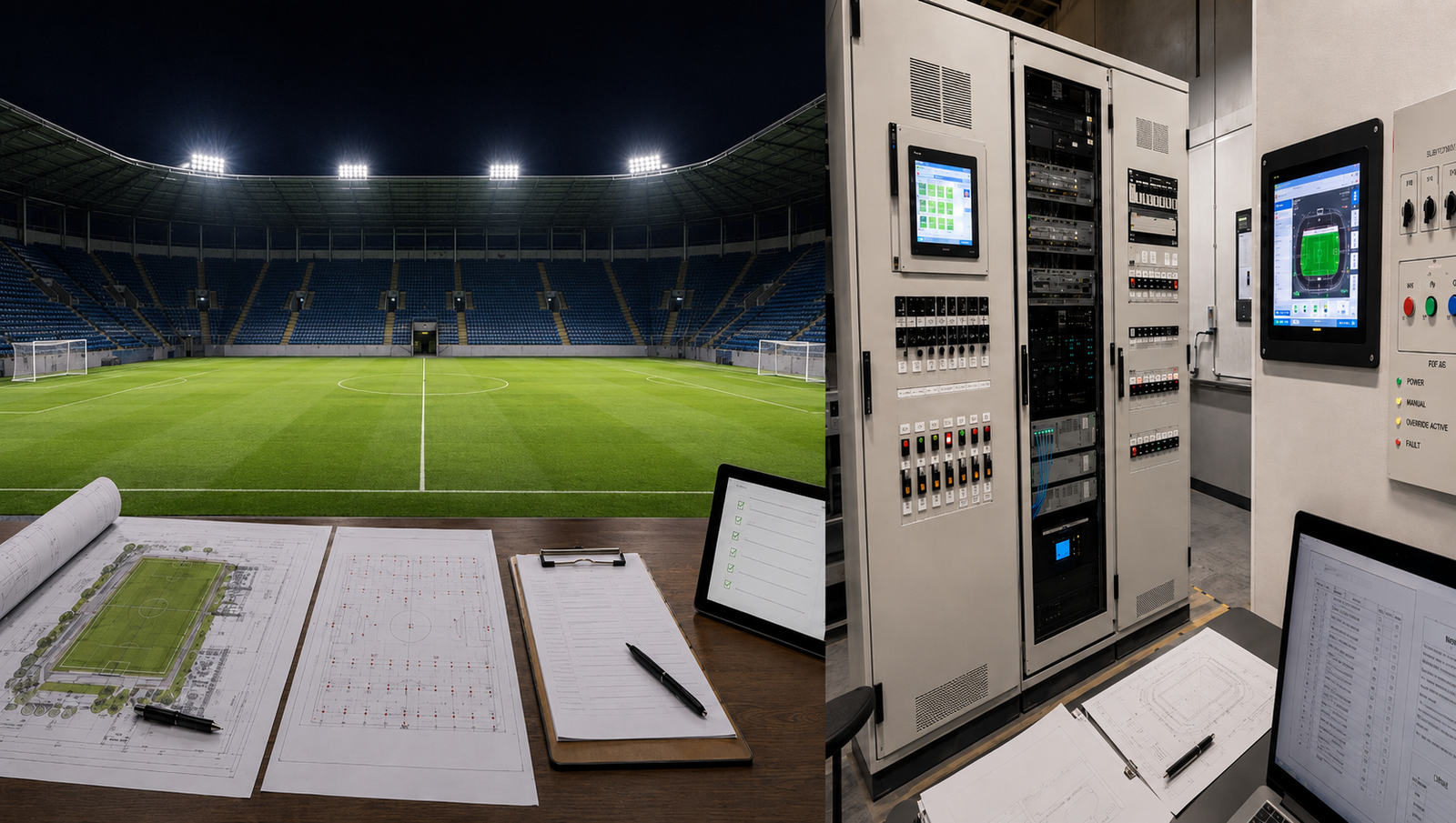
The LED driver is often treated as a hidden component inside a sports-lighting luminaire. In a high-power project, however, the driver architecture affects much more than whether the LEDs turn on.
It influences thermal exposure, service access, pole-top weight, cable design, dimming behavior, control addressing, flicker performance, spare-parts planning and the final commissioning process.
The industry is giving the driver greater strategic visibility. In July 2026, Signify announced that Xitanium would be elevated from a product family to a standalone Signify-endorsed brand, beginning with OEM LED drivers from August 2026. Signify’s current high-power driver portfolio also illustrates how sports-lighting electronics are increasingly designed around configurable output channels, DMX or D4i options, remote mounting, and long-distance connections.
The lesson for a sports-lighting project is not that one driver brand or architecture is always best. It is the driver must be selected, documented, and commissioned as part of the complete lighting system.
1. The Driver Is Part of the Lighting System
A high-power LED sports luminaire may contain one driver, several driver,s or a multi-channel remote power unit. Those components determine how electrical power is converted, how the LED modules are grouped, and what can be controlled.
The driver configuration can affect:
- The actual power delivered to each LED module
- The number of independently controlled channels
- Dimming range and response
- Flicker and temporal light behavior
- Surge protection strategy
- Power-on and communication-loss behavior
- Maintenance and replacement procedures
For this reason, a product model name and wattage are not enough. The ordered configuration should also identify the driver model, quantity, output settings, control protoco,l and mounting location.
2. Integrated and Remote Driver Architectures
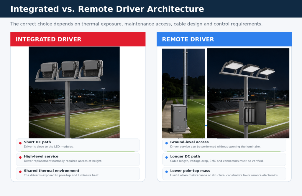
In an integrated architecture, the driver is mounted in or directly on the luminaire assembly. The DC connection between the driver and LED modules is short, whereas the AC feeder and control wiring typically reach the luminaire at a height.
This approach can create a compact product and simplify factory assembly. Its main project trade-off is service access: a driver replacement usually requires access to the pole top or luminaire position.
In a remote architecture, the driver is installed away from the luminaire—at the pole base, inside the pole, on a lower bracket or in a dedicated enclosure. This can reduce pole-top mass and make electronic maintenance possible from the ground or a lower working level.
The trade-off is a longer DC cable between the driver and LED load. Cable length, conductor size, voltage drop, insulation, connector rating, EMC behavior and the driver manufacturer’s maximum permitted distance must therefore be confirmed.
A hybrid architecture may also be appropriate, particularly where some functions are centralized while others remain at the luminaire.
3. Thermal Environment and Service Life
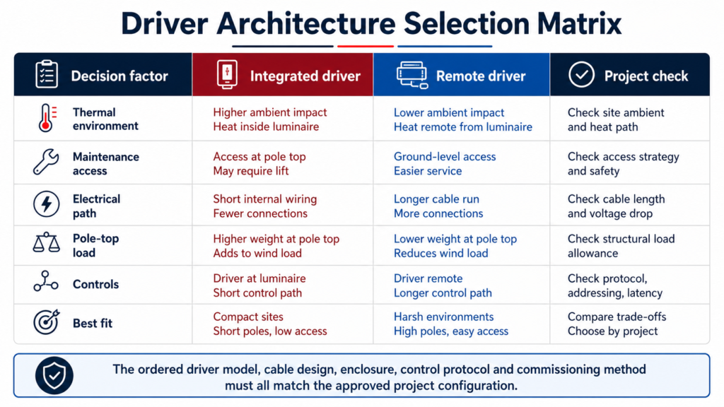
Drivers are temperature-sensitive electronic devices. Their operating temperature is affected by ambient conditions, enclosure design, solar exposure, internal losses and heat from nearby components.
An integrated driver shares the elevated environment of the luminaire. On an outdoor sports pole, this may include high daytime solar temperature, restricted airflow around the housing and heat from the LED modules during operation.
A remote driver can be placed in a more accessible or thermally controlled location, but this does not automatically guarantee a better environment. A poorly ventilated ground cabinet may experience high internal temperature, condensation, dust, water ingress or corrosive exposure.
The project team should confirm:
- Driver ambient and case-temperature limits
- Enclosure ingress protection
- Ventilation or heat-dissipation method
- Condensation control
- Coastal or corrosive-environment requirements
- Spacing between multiple drivers
- Whether the cabinet remains accessible without exposing live parts
Thermal design should be supported by the actual driver datasheet and the final enclosure arrangement, not only by a general lifetime statement.
4. Maintenance Access and Spare-Parts Strategy
Sports-lighting systems are installed at heights that can make even a simple electronic replacement expensive.
An integrated driver may require a lift, climbing system, field closure and nighttime verification after replacement. A remote driver can reduce high-access work, but the cabinet and cable system must be clearly labeled and protected against unauthorized access.
The maintenance plan should record:
- Pole ID and luminaire ID
- Driver ID and driver model
- Driver mounting location
- Circuit and control address
- Output current or power setting
- Connected LED modules
- Cable route and connector type
- Recommended spare quantity
- Replacement and recommissioning procedure
A spare driver is only useful when it matches the required voltage window, output current, control interface, firmware or configuration method and physical installation.
5. Cable Distance Is an Engineering Input
Remote drivers introduce a longer electrical path between the power conversion stage and the LED load.
The project should not assume that any driver can be installed at any distance. The design must consider:
- Maximum distance permitted by the driver manufacturer
- Conductor size and voltage drop
- Cable insulation and temperature rating
- DC connector and terminal ratings
- Routing through the pole and crossarm
- Separation from communication wiring
- EMC and surge behavior
- Maintenance isolation and lockout
- Cable replacement access
The DC cable should be treated as part of the driver-luminaire system. Changing its length, conductor or connection method may alter performance and should be reviewed before installation.
6. Broadcast Quality, Flicker and Driver Configuration
Professional sports projects may have camera and slow-motion requirements that are not captured by average illuminance alone.
Temporal light behavior depends on the complete electrical system, including the LED modules, driver topology, dimming level, control method and operating mode.
A driver described as suitable for broadcast applications should still be verified against the project’s camera requirements and test method. Important questions include:
- What is the flicker or temporal light performance at full output?
- What happens at reduced output?
- Does performance change between control protocols?
- Are all driver channels configured identically?
- Is the published result valid for the ordered luminaire and power setting?
- Does an RGBW or entertainment channel affect the essential white-light system?
The project file should connect the driver configuration to the tested luminaire configuration rather than relying on a generic driver claim.
7. Control Objects and Fail-Safe Behavior
A control protocol name does not explain what is actually being controlled.
Depending on the product architecture, a command may control:
- The complete luminaire
- One driver
- One LED or optical module
- A group of luminaires
- A white-light channel
- An RGBW channel
- A complete field zone
The design should define the control object, address structure, group logic and operating scenes.
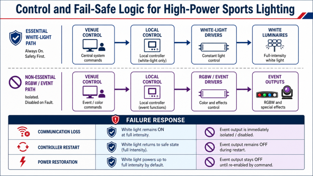
It should also define what happens when the network, controller or gateway fails. For a venue with essential white competition lighting and separate entertainment effects, a credible fail-safe strategy may:
- Maintain the last verified safe white-light level
- Move white light to a configured safe state
- Disable or isolate non-essential RGBW effects
- Preserve local manual override
- Restore normal control only after system health is confirmed
The exact behavior is project-specific. It must be agreed, programmed, tested and included in the handover documentation.
Current DLC NLC V5.2 requirements reflect the wider market direction toward qualified control systems, system integration and more structured control documentation. Sports venues may use different platforms, but the principle is relevant: control capability should be defined and verifiable, not described only as “optional.”
8. Structural and Installation Effects
Moving the driver changes the physical system.
An integrated driver adds mass and enclosure volume to the luminaire or pole-top assembly. A remote driver can reduce pole-top weight, but it introduces a cabinet, additional cable, mounting hardware and a different maintenance path.
Structural evaluation should still consider:
- Luminaire and bracket weight
- Effective projected area
- Center of gravity
- Crossarm loading
- Cable and junction-box placement
- Driver-cabinet foundation or bracket
- Wind, vibration and corrosion
- Safe separation from public areas
Lower pole-top weight does not automatically prove that an existing pole is acceptable. EPA, load path, crossarm condition and foundation capacity remain project-level checks.
9. The Minimum Driver Documentation Package
A project-ready driver package should contain enough information for the designer, contractor, integrator and facility operator to work from the same configuration.
Recommended records include:
- Driver manufacturer, model and ordering code
- Quantity of drivers per luminaire or pole
- Input voltage and frequency
- Output voltage window and current setting
- Number of independently controlled channels
- Dimming and control protocol
- Driver mounting location
- Maximum permitted cable distance
- DC cable and connector requirements
- Surge-protection arrangement
- Power-on, communication-loss and restart behavior
- Driver and luminaire identification method
- Spare-parts and replacement procedure
- Commissioning settings and final as-built record
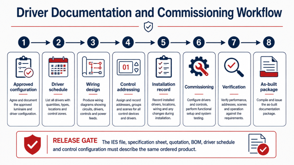
The specification sheet, IES file, quotation, BOM, driver schedule and control configuration should all describe the same ordered product.
10. A Practical Selection Workflow
The driver architecture should be selected after the project team understands the site and operating plan.
A practical sequence is:
- Confirm the luminaire power, LED-module arrangement and required output.
- Define the available input voltage and electrical distribution.
- Confirm the control object, protocol and operating modes.
- Evaluate pole-top access, maintenance cost and structural constraints.
- Review driver temperature limits and enclosure conditions.
- Calculate the required DC cable path for remote configurations.
- Confirm flicker and broadcast requirements where applicable.
- Define fail-safe and local manual-control behavior.
- Record the approved driver model, settings and mounting location.
- Verify the installed configuration during commissioning.
This process prevents a late driver change from creating conflicts in the wiring, control or photometric design.
11. Where ZC Lighting Fits
ZC Lighting’s credible role is to provide reliable sports luminaires together with the product and interface information needed by the wider project team.
For configurations involving remote drivers, separate white and RGBW functions or multiple driver channels, the final documentation should be matched to the ordered product.
Examples include:
- FL19 projects where remote driver placement is selected for service access
- FL21 projects where white-light and RGBW functions require clearly separated driver and control information
- FL18 high-power or broadcast-oriented projects where the exact driver and flicker configuration must be confirmed
- FL26 modular projects where driver quantity, module grouping and service strategy should be traceable
ZC should not claim ownership of the complete venue-control platform unless it is actually included in the contract. A more reliable position is to provide stable lighting hardware, clear driver configurations and control-ready interfaces that qualified partners can integrate.
Conclusion
The LED driver is not a minor accessory in a sports-lighting project.
It connects the electrical system, LED modules, control platform and maintenance plan. The choice between integrated and remote architecture affects thermal conditions, service access, cable design, structural loading, fail-safe behavior and final documentation.
The best architecture is not the one with the most features.
It is the one that is correctly matched to the project, clearly documented, safely installed and verified during commissioning.
Project Checklist
Before approving a sports-lighting driver configuration, confirm:
- Driver model and ordering code
- Number of drivers and output channels
- Integrated, remote or hybrid mounting
- Input voltage and output settings
- Maximum cable distance
- Dimming and control protocol
- Flicker requirements
- Communication-loss behavior
- Local manual override
- Driver and luminaire identification
- Spare-parts strategy
- Commissioning and as-built records
Share your project voltage, pole layout, control system and maintenance constraints for an initial technical review.