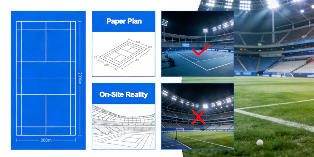
If the design simulation used one grid and the on-site acceptance test used another, the results are not comparable-so disputes are almost guaranteed. This guide turns measurement grids into a simple, repeatable sign-off process.
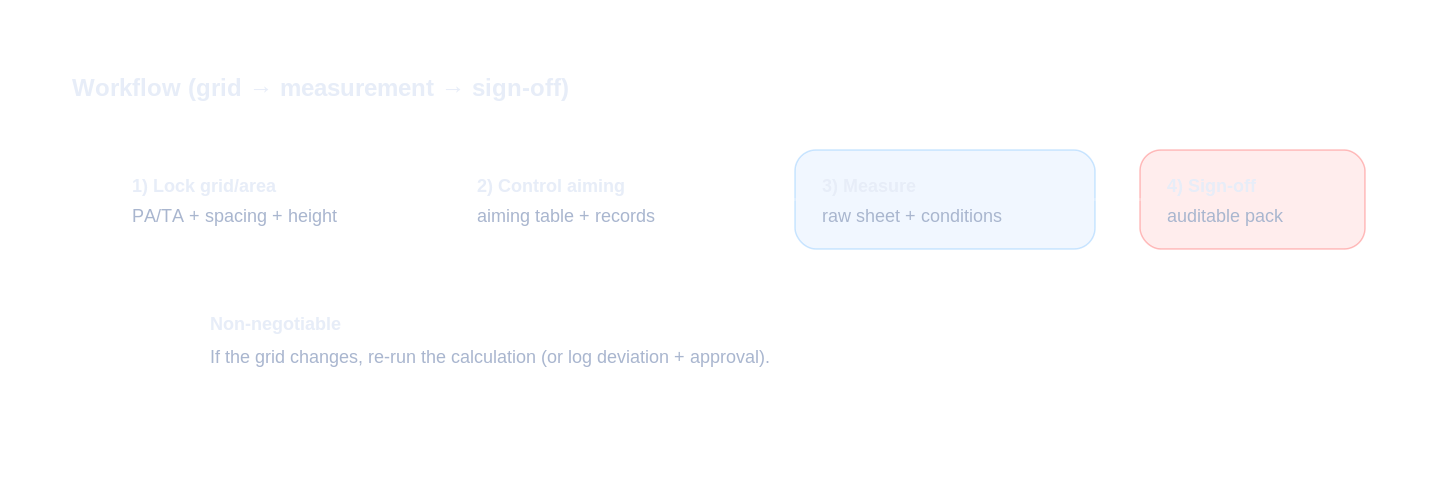
To pass sign-off consistently, lock the grid early, provide a point map + aiming table, and deliver an auditable measurement record package.
- Key takeaway #1: Treat the measurement grid as contract language: same grid in simulation and on-site tests.
- Key takeaway #2: Aiming angles are the hidden variable-record final aiming angles per pole.
- Key takeaway #3: An auditable sign-off pack (raw sheets + photos + as-built) prevents disputes after acceptance.
Table of contents
When this applies
Use this guide when your project involves commissioning and acceptance testing-especially if multiple parties are involved (owner, consultant, contractor, installer). It helps you prevent the classic situation: “the report says pass, but the field test says fail.”
Typical scenarios
- Consultant-led acceptance tests: the grid and reference area must be defined exactly.
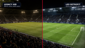
- Retrofits with fixed poles: aiming differences are the #1 source of unexpected measurement results.
- Multi-sport venues: different standards may imply different grids/areas-define which one controls sign-off.
- Fast-track projects: teams try to “save time” by simplifying measurement-often creating disputes.
Key requirements / metrics
This table lists the grid elements that most commonly trigger acceptance disputes.
| Grid / rule item | What it controls | Why it causes disputes |
|---|---|---|
| Reference area definition PA / TA |
Which part of the field is evaluated (playing area vs total area including run-off). | If design uses one area and commissioning measures another, results are not comparable. |
| Grid spacing / point count | How many points are measured and how sensitive uniformity is to hot spots. | Too few points can hide non-uniformity; changing spacing changes uniformity results. |
| Measurement height | Whether you measure on the surface or at a defined plane (depends on standard/tender). | Different heights can change readings (especially on uneven surfaces). |
| Maintained vs initial MF |
Whether the calculation uses a maintenance factor and what “pass” means over time. | If MF is used in design but ignored in acceptance criteria, arguments happen later. |
| Aiming confirmation | Whether installed angles match the simulated aiming table. | Small angle changes can shift hot spots and uniformity-even with the same fixtures. |
Definitions
A measurement grid is the set of points where illuminance is measured. The reference area defines which part of the venue is evaluated. Uniformity is highly sensitive to both-so you must treat the grid as part of the contract, not a flexible choice.
Typical target ranges
A “typical” best practice range is not a numeric value here-it’s a process rule:
- Use the tender/standard grid. If it exists, don’t change it.
- If absent, define a grid that is dense enough to reflect hot spots and edges, then lock it in writing.
- Keep sign-off consistent: same grid, same reference area, same measurement height, and documented conditions.
Step-by-step workflow
Your objective is comparability: the on-site test must measure the same “project reality” that the report simulated.
Inputs to collect (must-have)
- Tender acceptance rules: reference area, grid spacing/point count, measurement height, and required instruments.
- Calculation report assumptions: mounting height, aiming angles, maintenance factor (MF), surface notes.
- Site conditions: access to points, markings, and any deviations (temporary obstacles, surface changes).
Design decisions (key points)
- Lock the grid early. Put it into the report and the commissioning plan.
- Create a point map. Give the test team a point layout that matches the report.
- Build an aiming table and enforce it. Aiming changes are the most common hidden variable.
- Define a deviation process. If conditions differ, document and agree how results will be interpreted.
Verification & sign-off (how to accept)
- Pre-test alignment: confirm fixture orientation and aiming angles match the report before measuring.
- Measurement discipline: follow the agreed grid/height; record time, weather, and instrument details.
- Deliver an auditable pack: raw measurements + summary + photos + aiming records + the IES/spec pack.
Common mistakes
- Changing the grid on the day: breaks comparability and creates arguments about “what pass means.”
- Measuring too few points: uniformity becomes meaningless and hot spots are missed.
- No point map: teams measure different locations than the report assumes.
- Aiming not controlled: small aiming shifts cause large uniformity changes.
- Missing raw data: without raw sheets and conditions, results can’t be defended later.
Checklist / Template download
Measurement Grid Definition Sheet (CSV)
Lock reference area, grid rule, and measurement height before site tests.
Site Measurement Record (CSV)
A clean sheet to record raw measurements (for auditable sign-off).
Sign-off Pack Checklist (CSV)
A complete deliverables checklist to avoid missing documents at acceptance.
Commissioning Photo Checklist (TXT)
Make the sign-off pack undeniable with the right set of photos.