Optics selection is where stadium lighting projects are won or lost. The right distribution improves uniformity and cuts glare without increasing power; the wrong choice creates hotspots, spill, and sign-off disputes.
A tender-ready strategy uses a small optics family (3–6 options), provides IES/LDT files, and includes a pole-by-pole optics + aiming table for installation and sign-off.
- Key takeaway #1: Optics + aiming determine glare and spill; wattage only scales brightness.
- Key takeaway #2: Mixed optics (small set) usually beats one-beam-everywhere for uniformity.
- Key takeaway #3: Control photometric files and record aiming angles to prevent report-vs-reality disputes.
Table of contents
When this applies
Use this guide when you need to select optics/beam distributions quickly-especially for retrofits with fixed poles. It turns “wide vs narrow” into a repeatable workflow.
- Fixed poles: optics becomes your main “steering wheel”.
- Spill-sensitive venues: cut-off optics and low tilt angles matter.
- Broadcast: optics/aiming also affects Ev and camera quality.
- Tender review: you need IES/LDT and pole-by-pole optics/aiming table.
Key requirements / metrics
Key decision variables behind optics selection and how to verify each one.
| Decision element | What it impacts | Why it matters | How to verify |
|---|---|---|---|
| Throw distance | How far the light must travel. | Long throws need controlled optics to avoid wasted spill. | Simulate far-zone levels + edge performance. |
| Distribution & cut-off | Spread and high-angle light. | Controls glare and spill more than wattage. | Check glare metric + spill at sensitive points. |
| Mixed optics strategy | Using a few optics types across poles. | Improves uniformity and reduces hotspots. | Compare single vs mixed optics simulations. |
| Aiming angles | Where beams are directed. | Small changes shift hotspots and glare. | Aiming table + final angle records. |
Definitions
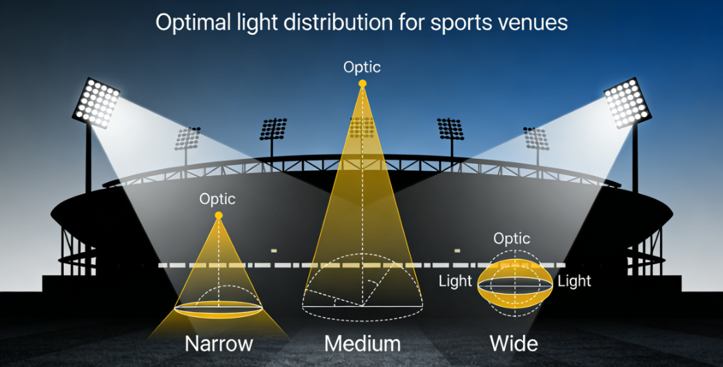
“Beam angle” is a simplified label. What matters is the distribution shape and cut-off behavior (high-angle output). Good optics targets the field while minimizing glare and spill.
Typical target ranges
There is no universal “best beam angle.” Use geometry-based logic:
- Long throws / higher poles: controlled optics to push light to far zones efficiently.
- Short throws / edge fill: wider optics can work with careful aiming.
- Spill-sensitive sites: prioritize cut-off optics and minimize high-angle output.
Step-by-step workflow
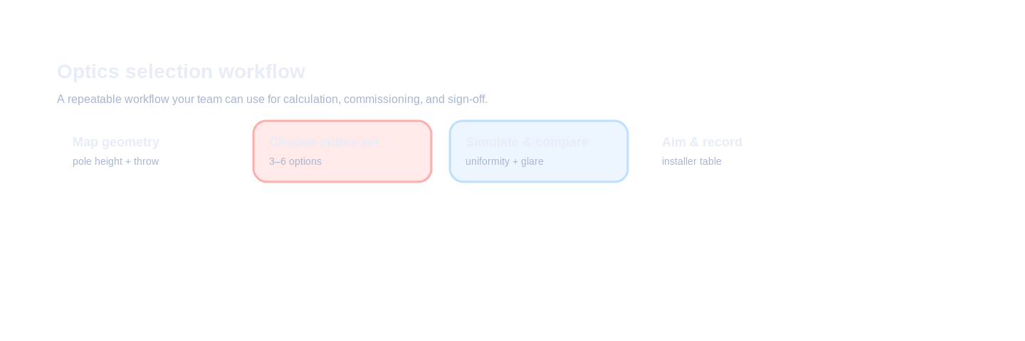
Do optics selection like engineering: geometry → optics family → simulation comparison → aiming plan → sign-off record.
Inputs to collect
- Pole height + locations: geometry defines throw distances.
- Field size + required area: playing area vs total area/run-off.
- Constraints: glare metric, spill limits, restricted aiming directions.
- Optics library: available IES/LDT for each optic.
Design decisions
- Map throw distances per pole. Far zones vs near/edge zones.
- Choose a small optics family (typically 3–6).
- Compare simulations: single vs mixed optics for uniformity, glare, spill.
- Finalize aiming table and control it during installation.
Verification & sign-off
- Provide IES/LDT set: keep an auditable file record.
- Record aiming angles: final angles and any shields used.
- Measure on site: verify grid results and check visible glare/spill concerns.
Common mistakes
- Choosing optics by wattage: optics determines distribution; wattage only scales it.
- One beam everywhere: creates hotspots and weak edge performance.
- Shields as first choice: optics + aiming should solve most issues.
- No IES/LDT control: mismatches cause report-vs-reality failures.
- Aiming not recorded: small shifts change glare/uniformity dramatically.
Checklist / Template download
Optics Selection Sheet (CSV)
Pole-by-pole optics decisions by throw distance.
Beam Angle Quick Rules (TXT)
Reusable selection logic for sales/PM teams.
Aiming + Optics Table (CSV)
Installer-friendly aiming record including optics.
Tender Optics Clause (TXT)
Spec language for optics + IES/LDT + aiming records.
FAQ
How do I choose beam angles for stadium floodlights?
Start from pole height, field size, and uniformity. Narrow optics for long throws and spill control; wider optics for short throws and edge fill—then validate glare/uniformity in simulation.
Is it better to use one beam angle for all poles?
Usually no. A mixed optics strategy using a small optics family often gives better uniformity and lower glare than forcing one beam everywhere.
Do shields replace good optics selection?
No. Shields are fine-tuning. Optics and aiming do most of the work for glare and spill control.
Why can a wide beam cause worse uniformity?
Wide beams can overspill and reduce useful intensity at far zones, creating bright near zones and dark far zones.
How do I keep optics selection tender-friendly?
Specify a small optics family (3–6) and provide IES/LDT plus a pole-by-pole optics/aiming table.