
Uniformity is essential in sports lighting, but it is not a complete measure of visual
comfort. Two fields can report the same minimum-to-average ratio and still feel very different to
players, spectators and cameras because the human eye sees bright sources, contrast, shadows and
direction—not only a grid of lux values.
Lighting and Field Geometry.
What uniformity tells us
Uniformity describes how evenly illuminance is distributed over a reference plane. UEFA’s
stadium-lighting guidance uses U1 and U2: U1 compares the minimum to the maximum value, while U2
compares the minimum to the average. UEFA also uses the minimum adjacent uniformity ratio for broadcast
applications to control rapid changes between neighbouring measurement points.
These metrics are valuable. They reveal dark zones, excessive peaks and abrupt transitions that may
affect ball tracking, player adaptation and camera exposure. However, they do not describe every source
of visual discomfort.
Minimum / maximum
Shows the total illuminance range across the measured plane.
Minimum / average
Shows how the lowest values compare with the normal adapted level.
Adjacent transitions
Controls the change between neighbouring points, especially for moving cameras.
Reference-plane result
Describes the selected horizontal or vertical plane—not what every observer sees.
| Metric | What it evaluates | What it does not guarantee |
|---|---|---|
| U1 (Emin / Emax) | The total illuminance range on one defined reference plane. | Comfortable source visibility or good modelling. |
| U2 (Emin / Eavg) | The relationship between the minimum and average illuminance on that plane. | Low glare, smooth adjacent transitions or comfortable spectator sightlines. |
| MAUR | The ratio between adjacent reference points and the risk of rapid local change. | Good visual comfort by itself. |
| Vertical illuminance | Light reaching players, faces and camera-facing planes. | Low glare or acceptable boundary spill. |
| Glare rating | View-dependent discomfort under the selected observer geometry. | Compliance with off-site obtrusive-light limits. |
Why a good U2 value can still feel uncomfortable
A uniformity ratio can remain unchanged even if the visible luminance of the fixtures increases. It can
also remain unchanged when the same light distribution is produced from lower poles, more aggressive
tilt angles or a different arrangement that places bright sources directly in the player’s sightline.
picture because it describes the minimum-to-average relationship on a defined plane. It is not a direct
comfort score and does not measure source luminance, discomfort glare, adaptation or observer
sightlines.
CIE 112 explains that outdoor sports glare depends on luminous intensity distribution, aiming, luminaire
number and arrangement, mounting height and the brightness of the illuminated area. UEFA similarly
emphasizes that player comfort must not be hindered by the lighting system. Uniformity is therefore one
part of a wider quality model.
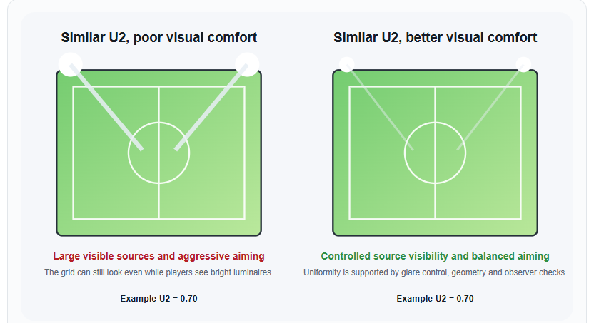
Illustrative engineering comparison—not measured project data. Both sides use the same schematic U2 value; the difference is visible source brightness, aiming and observer geometry.
What really affects visual comfort?
>
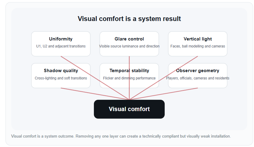
Visual comfort is a system resultUniformityU1, U2 and
adjacent transitionsGlare
controlVisible source
luminance and directionVertical lightFaces,
ball modelling and camerasShadow qualityCross-lighting and soft transitionsTemporal stabilityFlicker and dimming performanceObserver geometryPlayers, officials, cameras and residents
Visual comfort
Visual comfort is a system outcome. Removing any one layer can create a technically
compliant but visually weak installation.
Visible source luminance
A bright source near the normal viewing direction can dominate the scene even when the field is
evenly illuminated.
Observer adaptation
The same luminaire appears more severe against a dark background than against a brighter stadium
environment.
Light direction and modelling
Horizontal uniformity does not guarantee good face, ball or body modelling. Cross-lighting and
vertical illuminance matter.
Shadow structure
Uniform lux values can coexist with hard multiple shadows if the lighting directions are poorly
balanced.
Reflections and surface contrast
Wet turf, glass, glossy floors and light-coloured structures can create reflected brightness
outside the standard field grid.
Temporal behaviour
Flicker, unstable dimming or scene-to-scene imbalance can affect visual performance without
changing the static uniformity ratio.
Players, spectators and cameras do not share one viewing condition
A player tracks the ball through rapidly changing directions. A goalkeeper may look toward a fixed pole
group for long periods. Spectators look across the field from elevated positions, while broadcast
cameras evaluate vertical light, colour, flicker and adjacent transitions. A project can therefore meet
one reference-plane requirement while underperforming for another observer.
UEFA recommends evaluating glare at multiple observer positions and directions. The guidance also notes
that calculated uniformity may be higher than the values measured after installation, which is why
design margins and commissioning checks are important.
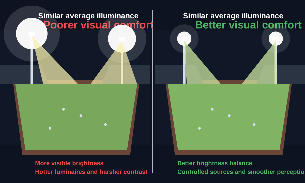
and similar U2 can still produce different visual comfort when source brightness and overall
brightness balance change.
Three examples where uniformity can mislead
1. A compact court with low mounting height
The court may achieve an acceptable U2 value, but players looking upward for a lob can see the luminous
face of a fixture at close range. The solution may involve different pole positions, more suitable
optics or shielding—not a higher lux target.
2. A community football field with one common tilt angle
Using the same aiming angle for every fixture can simplify installation and still produce a smooth
horizontal grid. However, the far-zone fixtures may be over-tilted and visible from the opposite
touchline. A near-, mid- and far-zone approach usually produces better control.
3. A stadium with strong horizontal performance but weak vertical balance
The pitch can appear even from above while players’ faces, the ball and camera-facing planes are less
consistent. Broadcast projects therefore require vertical illuminance and directional balance in
addition to horizontal uniformity.
A better design workflow: uniformity plus visual comfort
Define the observer groups
List players, officials, spectators, cameras, drivers and nearby residents before finalising pole
and luminaire positions.
Set the photometric targets
Confirm horizontal and vertical illuminance, U1, U2 and any adjacent-uniformity or broadcast
requirements.
Build the geometry first
Use appropriate mounting height, setback and structural positions so the system does not rely on
excessive tilt.
Assign target zones
Use different distributions or aiming strategies for near, middle and far areas instead of
forcing one beam to do every job.
Evaluate glare and source visibility
Review critical sightlines and use the applicable outdoor glare method rather than assuming
uniformity guarantees comfort.
Commission the installed system
Measure the grid, inspect observer routes, record final angles and retest after any adjustment.
A visual-comfort review checklist
| Design question | Uniformity answers it? | Additional check |
|---|---|---|
| Are there dark zones on the playing surface? | Yes, partly | Review U1, U2, grid resolution and adjacent transitions. |
| Can players see bright luminous faces in normal play? | No | Review observer positions, source luminance, tilt and shielding. |
| Are faces and the ball modelled clearly? | No | Review vertical illuminance and cross-lighting directions. |
| Will cameras experience rapid exposure changes? | Not by U2 alone | Review MAUR, vertical planes and camera directions. |
| Does the system remain comfortable in training mode? | No | Review scene grouping, output balance and adaptation. |
| Is off-site light controlled? | No | Review boundary illuminance, intensity, backlight and uplight. |
How product selection fits into the comfort equation
A product cannot guarantee visual comfort by itself, but its optical platform can make a good project
easier to achieve. Compact court projects may benefit from the long optical surface and optional visor
choices of PL08. Projects with sensitive
upward-light or boundary requirements may use a full-cutoff approach such as FL20. Larger fields may require different
distributions and output levels across one coordinated design rather than one identical fixture setup
everywhere.
The selection should always follow the venue geometry and observer needs. A higher-efficiency or
higher-output luminaire is not automatically more comfortable if its visible brightness and aiming are
poorly controlled.
Frequently asked questions
What is the difference between U1 and U2?
U1 compares minimum to maximum illuminance. U2 compares minimum to average illuminance. Both
describe distribution on a selected reference plane.
Can two designs have the same U2 and different glare?
Yes. U2 can stay the same while source luminance, tilt, pole height, fixture arrangement and
observer sightlines change.
Is MAUR the same as uniformity?
It is an adjacent-uniformity metric. It focuses on the transition between neighbouring points and
is particularly useful for broadcast camera movement.
Does better uniformity always require more fixtures?
No. Better pole geometry, optical selection, target-zone planning and cross-lighting can improve
uniformity without simply adding fixtures.
Sources and further reading
- UEFA Stadium Lighting Guide 2023: Uniformity
- UEFA Stadium Lighting Guide 2023: Minimum Adjacent Uniformity
Ratio - UEFA Stadium Lighting Guide 2023: Evaluating Glare
- CIE 112-1994: Outdoor Sports Glare Evaluation
- ZC Lighting: Why
Low-Glare Sports Lighting Is Becoming a Project Requirement
Need a sports-lighting design that balances uniformity and comfort?
ZC Lighting can support IES files, product selection, application matching and photometric design for
compact courts, community fields and stadium projects.