Sports-lighting projects close to homes are often approved or rejected at the property boundary—not at the centre of the field. Good design therefore starts with receptor locations, pole geometry, aiming and operating hours before the fixture count is finalised.
Why residential-area projects require a different design process
A community field, school court or padel facility may operate only a few metres from homes, roads or ecological receptors. The field still needs useful illuminance, but the project must also manage spill light, backlight, high-angle glare, reflected light and the time of night when the system is operating.
CIE 150:2017 provides guidance for limiting the effects of obtrusive light, and the ILP GN01/21 is widely used for applying these ideas in practice. The shared principle is that unwanted light should be controlled through appropriate design before relying on remedial measures after complaints begin.
Start with a receptor map—not a luminaire schedule
Before choosing poles or fixtures, mark every sensitive receptor around the site: ground-floor and upper-floor windows, gardens, road approaches, pedestrian routes, ecological edges and any dark-sky or conservation areas. Record the receptor height and viewing direction, because a second-floor bedroom can see a luminous face that is hidden from the ground-level boundary.
The environmental context also matters. CIE and ILP guidance use environmental zones to reflect the surrounding level of ambient brightness and sensitivity. The project team should confirm which limits, planning conditions and assessment planes apply locally rather than copying values from another country or venue.
Setback: create distance before increasing tilt
Setback is the horizontal distance between the lighting position and the sensitive boundary or receptor line. More distance can reduce apparent source size and provide space for the beam to reach the field without crossing the property boundary at an aggressive angle. However, there is no universal setback value that works for every project.
The correct distance depends on pole height, optical distribution, field size, target zone, boundary orientation, receptor height and the allowable off-site criteria. A short setback may still work with a suitable full-cutoff or asymmetric distribution, while a long setback can fail if the fixtures are over-tilted or aimed past the field.
Higher optical pressure
The design must control visible source brightness and rear spill very tightly because the receptor is close to the luminaire position.
More aiming flexibility
Distance can reduce intensity at the receptor, but it may require higher poles or different optics to maintain useful field coverage.
More visible source risk
Lower mounting can increase the chance that players and residents see the luminous face directly.
Potentially gentler aiming
Higher mounting may reduce tilt severity, but structure, visual impact, wind load, cost and planning limits must be checked.
Pole height and setback must be solved together
Trying to minimise pole height without considering throw distance often forces fixtures to aim closer to horizontal. That can increase glare inside the field and push more light toward the residential side. Conversely, simply increasing pole height is not always the answer, because taller structures can create planning and structural concerns.
The better approach is to test height and setback as a pair. The selected geometry should allow the optical distributions to cover near, middle and far zones while keeping the most sensitive cut-off direction under control.
Aiming: direct every fixture to a defined target zone
Each luminaire should have a target point or target zone. Near-side fixtures should not be aimed through the field simply because the same beam angle is being used everywhere. Far-side coverage should not be created by tilting a wide distribution close to horizontal.
For a four-pole football layout, the pole groups can be divided into near, middle and far responsibilities, with cross-lighting used to support modelling and uniformity. The residential-side poles require special attention to rear intensity, while the opposite poles should not be aimed beyond the field toward the homes.
- Use asymmetric or full-cutoff distributions where the project needs a hard boundary on one side.
- Limit tilt by solving the mounting height and setback first.
- Check the visible luminous surface from upper-floor windows, not only at the fence line.
- Model the boundary on both horizontal and vertical planes where required.
- Record the final aiming schedule so the installation can be verified after construction.
Separate spill light, backlight and uplight
These terms are related but not interchangeable. Spill light reaches outside the intended playing area. Backlight travels behind the lighting position. Uplight is emitted or reflected toward the sky. A project may control one and still perform poorly on another.
| Risk | Typical cause | Design response |
|---|---|---|
| Light entering windows | Beam overshoot, high rear intensity or receptor above the assessed plane | Review vertical receptor planes, optics, aiming and shields. |
| Bright visible fixtures | Low mounting, excessive tilt or unshielded source in the viewing direction | Change geometry, aim or source shielding before increasing output elsewhere. |
| Road or pedestrian distraction | High intensity in approach directions | Add observer positions along the route and assess the most critical viewing angles. |
| Skyglow | Direct uplight or reflected light from excessive field levels | Use targeted optics, appropriate lumen density and curfew/dimming controls. |
| Rear spill behind poles | Wide symmetric beams or unsuitable visor geometry | Use asymmetric distributions, rear shields or a different pole line. |
When visors and shields help—and when they do not
Visors can reduce direct visibility and rear spill from selected directions, but they are not a universal correction. A shield may cut useful light, change the distribution or require additional fixtures if it is applied after the design is complete. It can also fail to solve a problem caused by low pole height or incorrect setback.
Use a visor when the design model shows a clear sensitive direction and the modified photometric file confirms that useful field performance is maintained. Do not treat an accessory as a substitute for suitable geometry.
Operating hours and control scenes are part of spill-light control
Even a well-aimed field can create conflict if full competition output remains active for cleaning or informal use. A responsible control strategy should include separate competition, training, maintenance and security scenes, together with automatic shut-off or curfew settings where required.
DarkSky’s sports-lighting program combines limits on spill and glare with curfew requirements and field verification. Local planning authorities may also request operating hours, beam orientations, contextual lux-spill maps and the impact on nearby dwellings, roads or habitats. These items should be prepared as part of the initial submission, not after the first objection.
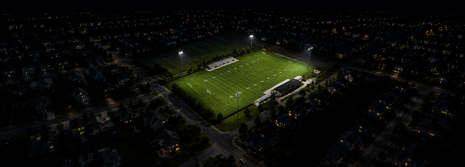 Illustrative sensitive-edge condition—not proof of compliance. Nearby homes remain
comparatively dark, but source visibility, upper-floor receptor planes and rear intensity still
require calculation and night-time verification.
Illustrative sensitive-edge condition—not proof of compliance. Nearby homes remain
comparatively dark, but source visibility, upper-floor receptor planes and rear intensity still
require calculation and night-time verification.What to include in a planning or client submission
Site and receptor plan
Show poles, field, boundaries, nearby windows, roads, ecological edges and receptor heights.
Fixture and aiming schedule
List luminaire model, optics, wattage, bracket position and horizontal and vertical aiming angles.
Field performance
Provide maintained illuminance, uniformity and any vertical or glare requirements for the class of play.
Off-site calculations
Include the boundary or receptor planes required by the authority, with clearly defined calculation spacing and height.
Control and curfew plan
Explain each scene, output level, operating schedule and automatic shut-off logic.
Commissioning method
State how aiming, field measurements and off-site performance will be checked after installation.
| Submission output | What to show | Why it matters |
|---|---|---|
| Receptor-point schedule | Point ID, coordinates, assessment height, view direction and receptor type. | Prevents ground-level boundary checks from missing upper-floor windows. |
| Boundary and window planes | Horizontal boundary illuminance and vertical illuminance at selected receptor planes. | Separates field performance from off-site impact. |
| Source-intensity review | Critical fixture groups and directions toward each receptor. | Identifies bright visible sources even when boundary lux looks modest. |
| Aiming schedule | Fixture ID, optic, wattage, horizontal aim, vertical aim and visor. | Connects the calculation to installation and commissioning. |
| Control schedule | Competition, training, maintenance, security, curfew and automatic shut-off. | Shows how full output is limited to the periods that need it. |
| Post-installation verification | Field grid, receptor measurements, photographs and corrective-action record. | Confirms the installed system matches the approved design. |
Relevant ZC Lighting directions
Compact court projects may use PL08 where a long optical surface, flexible mounting and optional visors suit the court geometry. Projects requiring a stronger cut-off may consider a full-cutoff platform such as FL20. Flexible multi-field projects may use a modular platform such as FL26, provided the final optics and aiming are selected for the actual boundary conditions.
These are product directions rather than automatic prescriptions. The project geometry, environmental limits and photometric model should determine the final choice.
Frequently asked questions
Is there a universal minimum setback for sports lighting near homes?
No. Setback must be solved with pole height, beam distribution, field dimensions, receptor height, aiming and local limits.
Can a visor eliminate spill light?
A visor can reduce light in selected directions, but it cannot correct every geometry or aiming problem and may reduce useful field light.
Should the boundary be checked only at ground level?
Not always. Upper-floor windows or elevated roads may be more critical than the ground-level fence line.
Do lower poles always reduce neighbour impact?
No. Lower poles can require more aggressive aiming and make the luminous face more visible. The complete geometry must be evaluated.
Sources and further reading
- CIE 150:2017: Guide on the Limitation of the Effects of Obtrusive Light
- ILP GN01/21: The Reduction of Obtrusive Light
- DarkSky Outdoor Sports Lighting Guidelines
- LTA Padel Court Construction Guidance Note 2025
- ZC Lighting: Why Low-Glare Sports Lighting Is Becoming a Project Requirement
Planning a sports facility close to homes or other sensitive boundaries?
ZC Lighting can support application matching, IES files, photometric simulation and product selection for compact courts, community fields and larger sports venues.