
Table of Contents
Primary category: Installation & Commissioning. Secondary topics: Optics, Photometrics and Maintenance.
Why glare verification matters after installation
FMany sports-lighting projects pass the design review and still require adjustment after installation. The reason is simple: glare is highly sensitive to the actual luminaire position, aiming angle, observer direction, visible source brightness and surrounding background. Small deviations that appear minor on a drawing can become obvious when a player looks toward a pole or when a resident sees the installation from an upstairs window.
The CIE 112 outdoor sports glare system can be used for predicting or checking glare, but its validity is limited to specified viewing conditions. FIFA also notes that glare can be assessed by calculation and, where appropriate, by high-dynamic-range imaging during commissioning. The important point is that the handover process must connect the design model with the real installation.
What can change between the model and the finished site?
Prepare the verification plan before going to site
A useful glare inspection starts before the lights are switched on. The commissioning team should prepare a field package containing the approved calculation, pole schedule, luminaire ID list, horizontal and vertical aiming angles, control scenes, target illuminance values, critical observer points and any planning or boundary-light conditions.
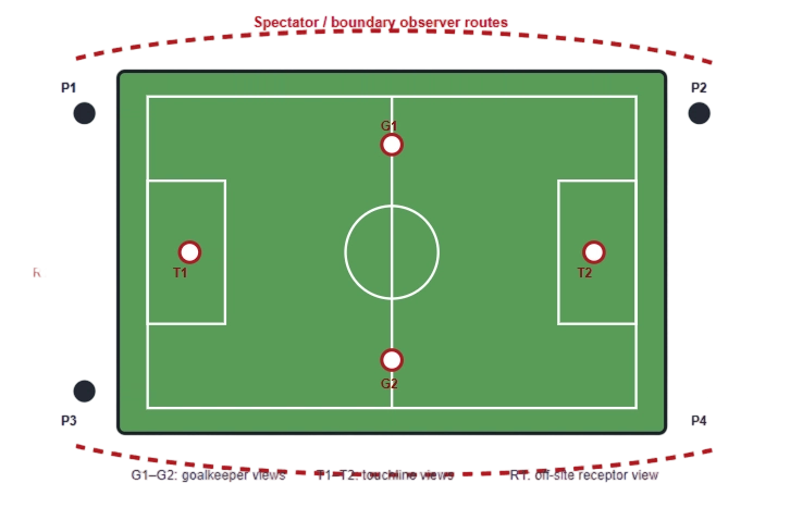
For compact courts, observer points should include baseline, service-line and spectator directions. For football or rugby fields, include common player sightlines, goalkeeper views, officials’ positions and the main spectator side. Where homes, roads or ecological receptors are close to the venue, add a separate off-site route.
A step-by-step on-site glare verification method
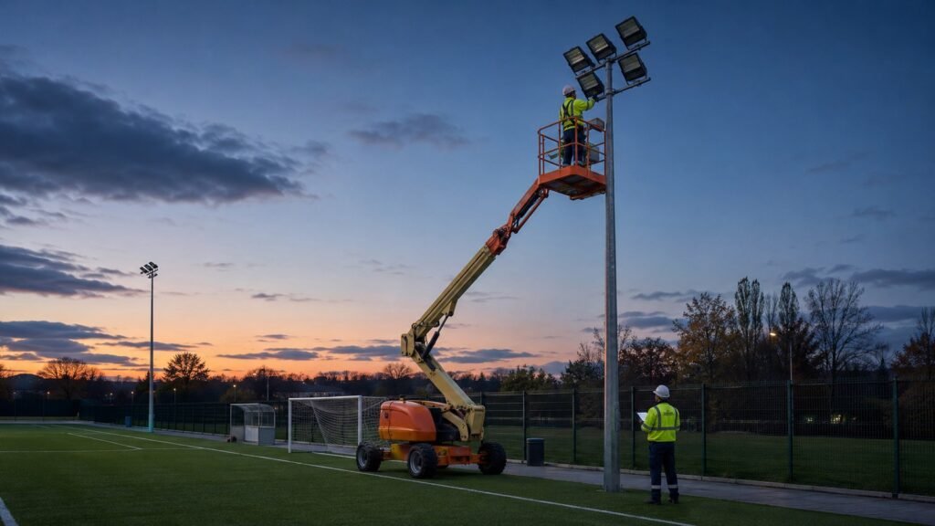
What should be measured—and what should only be observed?
Measurement distinction: a lux meter verifies illuminance on a defined plane. It does not directly quantify the apparent luminance of a floodlight in the observer’s field of view. Use the glare method named in the project specification—such as a CIE 112 calculation, a validated luminance/HDR method or a structured visual assessment with fixed observer geometry.
| Verification item | Typical method | Purpose |
|---|---|---|
| Horizontal illuminance | Calibrated lux meter on the approved grid | Confirms average level and field uniformity after aiming changes. |
| Vertical illuminance | Meter held on specified vertical planes | Checks player modelling and camera-facing performance where required. |
| Glare rating | Design calculation or validated field method | Provides a standardised comparison under defined observer positions and directions. |
| Boundary light | Measurement on agreed boundary or receptor plane | Confirms compliance with planning, environmental or neighbour-impact conditions. |
| Visible source condition | Structured observer route with pole and direction record | Identifies the specific luminaire group responsible for discomfort. |
| Control scene | System log and scene verification | Ensures the measured condition matches normal venue operation. |
Common glare patterns and their likely causes
| Observed pattern | Likely cause | First corrective action to test |
|---|---|---|
| One bright source dominates from a baseline or touchline | Fixture is over-tilted, rotated or aimed across the main sightline | Verify fixture ID and angles before changing optics or adding shields. |
| Several sources are visible as a bright row | Pole height, setback or common tilt is exposing the luminous faces | Review the full pole group; a single-fixture correction may not solve the geometry. |
| Field remains uniform but players still report discomfort | Uniformity is acceptable, but source luminance or observer position is poor | Reduce direct source visibility and redistribute overlap with adjacent luminaires. |
| Complaint occurs only at reduced output | Dimming scene changes contrast or leaves isolated bright fixtures active | Review scene grouping and output balance, not only full-power aiming. |
| Glare appears after rain | Specular reflections from wet surfaces, glass or nearby structures | Inspect reflected paths and consider source position, shielding or surface treatment. |
What the final acceptance report should contain
- Final fixture schedule with luminaire IDs, optics, output setting and installed aiming angles.
- Measured illuminance results and the exact operating scene used.
- Observer positions, viewing directions and any glare calculation or validated imaging records.
- Boundary or receptor measurements where the project is close to homes, roads or sensitive land.
- A list of adjustments made during commissioning and confirmation that the affected areas were remeasured.
- Photographs used for orientation and documentation, clearly separated from calibrated photometric evidence.
- Signed acceptance criteria, remaining limitations and the procedure for future re-aiming after maintenance.
| Observer point | Viewing direction | Pole / fixture | Scene | Finding | Corrective action | Retest |
|---|---|---|---|---|---|---|
| G2 | Goalkeeper to northwest pole | P1-L3 | Match 100% | One dominant visible source | Verify ID; reduce vertical aim by 2° | Pass |
| T1 | Touchline toward opposite pole group | P2-L1/L2 | Training 60% | Acceptable brightness balance | None | Pass |
| R1 | Residential receptor toward east pole line | P2/P4 | Match 100% | Rear intensity above project target | Re-aim and fit validated visor | Retest required |
Important limitations
The CIE glare-rating method is useful, but it does not replace every player or off-site assessment. Its applicability is defined by the viewing geometry, and the effect of looking directly upward into a luminaire must be controlled mainly through sensible siting, mounting and aiming. For projects near residential areas, glare inside the venue and obtrusive light outside the venue should be assessed as related but separate problems.
DarkSky’s outdoor sports-lighting program is one example of a process that combines design submission with field verification. This reinforces a practical lesson for all projects: approval calculations should be followed by site checks under the operating conditions that matter.
Frequently asked questions
Can glare be verified with a normal lux meter?
A lux meter is essential for illuminance and boundary measurements, but it does not directly describe the apparent brightness of a luminaire in the observer’s view. Use the metric and method required by the project specification.
Should fixtures be adjusted while players are on the court or field?
No. Aiming and electrical work should follow site safety rules, with the playing area controlled and personnel kept clear of unsafe operating zones.
Can a project pass uniformity tests and still fail glare verification?
Yes. Uniformity describes the distribution of illuminance on a reference plane. It does not fully describe source brightness, sightline exposure or off-site impact.
When should glare be rechecked?
Recheck after major re-aiming, fixture replacement, bracket work, pole movement, control-scene changes or complaints that indicate the installed condition has changed.
Sources and further reading
Need a clearer sports-lighting commissioning package?
ZC Lighting can support photometric files, aiming schedules, fixture identification, application matching and project documentation for court, field and stadium projects.