In This Article
- Quick Answer: What Should You Compare?
- Start With the Road, Not the Product
- Select Optical Distribution Before Final Wattage
- Why Wattage Is Not a Roadway Design Target
- Coordinate Pole Height, Spacing, Arm and Tilt
- Evaluate Uniformity, Glare, CCT and Visual Quality
- Check Outdoor Reliability and Serviceability
- Decide Whether the Project Needs Smart-Ready or Connected Lighting
- Matching ZC Lighting Street Light Families to the Project
- Street Light RFQ Checklist
- When Two Compliant Proposals Give Different Answers
- Inspect the Sample With the Installation Crew
- Before You Release the Purchase Order
- Sources and further reading
- FAQ
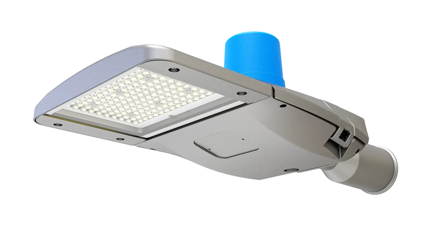
A street light quotation can look complete and still leave the main question unanswered: will this fixture light this road properly? A wattage, a lumen figure and a photograph cannot show what happens halfway between poles or outside a resident’s window. Start with the road drawing and the lighting requirements. Then ask each supplier to calculate the same layout. That gives you a basis for comparing the optic, power setting and installation cost before committing to a model.
Quick Answer: What Should You Compare?
Before approving a fixture, compare the road category, carriageway width, pole height, pole spacing, setback, arm length, tilt, mounting orientation, target lighting criteria, surface conditions, environmental exposure, control method and maintenance plan. Wattage becomes meaningful only after these inputs are known.
1. Start With the Road, Not the Product
Roadway lighting is an application problem. A residential street, a multi-lane arterial road, a rural highway and an industrial access road have different traffic speeds, pedestrian activity, conflict zones and visual tasks. The design criteria should therefore come from the authority having jurisdiction, the project specification or a recognized roadway lighting practice applicable to the destination market.
Do not copy a lux value from another project without checking the road classification and measurement method. Some specifications are based primarily on illuminance, while others emphasize pavement luminance, uniformity, glare or surrounding-area considerations. The maintained target also differs from the initial measured value because dirt and lumen depreciation must be considered.
| Project input | Why it matters | Evidence to request |
|---|---|---|
| Road type and use | Defines the visual task, traffic conflict and likely lighting class. | Road classification, drawings and authority criteria. |
| Road and sidewalk geometry | Controls the required beam reach and lateral distribution. | Width, lanes, median, sidewalk and setback dimensions. |
| Pole arrangement | Changes overlap, uniformity and glare. | Pole height, spacing, arm length, tilt and mounting side. |
| Environment | Affects corrosion, sealing, surge protection and thermal design. | Temperature range, coastal exposure, dust and electrical conditions. |
2. Select Optical Distribution Before Final Wattage
Roadway optics shape where the luminaire sends light. The common Type II, Type III and Type IV descriptions are useful starting points, but the label alone does not prove performance. Two manufacturers can offer distributions with the same family name yet produce different candela patterns, backlight, high-angle intensity and spacing capability.
Type II optics
Type II distributions are often considered for narrower roads, paths and longer longitudinal spacing where the luminaire needs to project light along the roadway without excessive lateral spread. Suitability still depends on mounting height, setback and the exact photometric file.
Type III optics
Type III distributions generally provide broader lateral coverage and are frequently evaluated for typical streets, arterials, parking lanes and wider carriageways. They can help cover more road width, but the designer must check backlight and glare near property boundaries.
Type IV and project-specific optics
Forward-throw distributions can be useful where luminaires are mounted near the edge of a broad area. Intersections, curves, medians and asymmetric road sections may need a different optic or a mixed-optic schedule. The final choice should be confirmed with an IES or LDT photometric file in the actual calculation model.
3. Why Wattage Is Not a Roadway Design Target
Wattage describes electrical input, not useful light on the pavement. Lumens describe total light output, but they still do not show where the light lands. A lower-wattage luminaire with an appropriate distribution can outperform a higher-wattage unit that sends excessive light behind the pole, above the useful zone or into glare angles.
For product comparison, examine system efficacy together with the intensity distribution, driver losses, operating temperature, lumen maintenance assumptions and control profile. Then compare total connected load for the whole road, not only watts per fixture. A design using fewer high-power luminaires is not automatically better if it creates dark zones or excessive glare, and a design using more fixtures may increase poles, cabling and maintenance points.
Do not specify
“Replace every 250 W lamp with a 100 W LED” without calculations.
Specify instead
Maintained performance, optical file, layout, controls, environmental requirements and acceptance method.
4. Coordinate Pole Height, Spacing, Arm and Tilt
Pole height affects beam spread, glare perception and the area covered by each luminaire. Greater mounting height can improve overlap and visual continuity, but it may require more output and creates more difficult maintenance access. Lower poles can create stronger brightness contrast and may require closer spacing. There is no universal spacing-to-height ratio that replaces a calculation.
Setback and arm length determine the luminaire position relative to the carriageway. Tilt can extend reach, but excessive tilt increases high-angle light, glare and spill. A well-designed roadway luminaire should normally use its optic to distribute light rather than depending on aggressive aiming. Existing poles also require checks for tenon diameter, arm orientation, structural condition, wind loading and cable entry.
For retrofit work, survey a representative sample of poles rather than assuming that every installation matches the original drawing. Field modifications, different arm lengths and settlement can change the real geometry enough to affect photometric performance.
5. Evaluate Uniformity, Glare, CCT and Visual Quality
Average illuminance alone can hide poor performance. A road can have enough average light while still containing dark patches between poles or uncomfortable brightness near each luminaire. Review the applicable uniformity metric, minimum values, threshold increment or other glare criteria required by the project. For pedestrian areas, vertical visibility and facial recognition may also matter.
Correlated color temperature should fit the local policy, surrounding land use and visual task. Higher CCT is not a substitute for better optics. Many residential and environmentally sensitive projects prefer warmer light to improve comfort and reduce unnecessary short-wavelength content, while transport routes may use a different project requirement. CRI is also application-dependent; the buyer should avoid paying for a higher value unless it supports the visual task or specification.
Ask for a complete photometric report showing calculation points, maintenance factor, road surface assumption and luminaire tilt. A single false-color rendering without inputs is not enough for technical approval.
6. Check Outdoor Reliability and Serviceability
Street lights operate through heat, rain, dust, vibration, voltage disturbance and long daily operating cycles. The relevant specification may include ingress protection, impact resistance, surge protection, electrical class, ambient temperature, corrosion treatment and vibration testing. These values must be confirmed for the exact model, wattage and configuration being purchased.
Serviceability deserves equal attention. Tool-free access, a separated driver compartment, safe power isolation, replaceable control nodes and clear spare-part support can reduce work at height. For a municipal fleet, the cost of a service visit can exceed the price difference between two luminaires, so maintenance design should be part of tender evaluation.
7. Decide Whether the Project Needs Smart-Ready or Connected Lighting
A photocell provides basic dusk-to-dawn switching. A dimmable driver can support scheduled reductions. A networked control node can add remote status, energy data, fault alerts and adaptive scenes. These are different levels of functionality and should not be treated as interchangeable.
If a city may add controls later, a standardized receptacle can protect the upgrade path. NEMA and Zhaga interfaces serve different ecosystems and electrical architectures. The luminaire, driver and node must be checked as a complete compatible system. A socket label by itself does not guarantee every monitoring or control function.
8. Matching ZC Lighting Street Light Families to the Project
ZC Lighting positions SL03, SL04 and SL05 for different budget, flexibility and municipal requirements. The right model should be selected from verified project data, not from a generic “best product” claim.
| Series | Current positioning | Typical buyer reason to evaluate | Confirm before order |
|---|---|---|---|
| SL03 | Budget-oriented, power-tunable street light family. | Distributors and mixed road portfolios seeking configuration flexibility. | Exact wattage, optics, controls, mounting and certificates. |
| SL04 | Cost-effective roadway luminaire with maintenance and sensor-ready emphasis. | Secondary roads, community areas and retrofit-focused tenders. | Approved datasheet, driver access, optical code and ordered control option. |
| SL05 | Municipal and urban road family with wider configuration and smart-interface options. | Projects needing multiple roadway distributions, field serviceability or smart-ready planning. | Final driver, socket, optic, protection and regional certification package. |
9. Street Light RFQ Checklist
A useful request for quotation should include the road plan, cross-section, pole coordinates, mounting height, arm details, supply voltage, target standard, control requirement and environmental conditions. State whether the project is new construction or retrofit and whether existing poles must be reused. Ask the supplier to return the proposed luminaire schedule, photometric files, calculation report, product datasheet, wiring information, installation method and confirmed compliance documents.
For large orders, a pilot section can validate installation, light distribution, glare perception, control commissioning and maintenance access before full deployment. Acceptance criteria should be agreed before the pilot is installed, including where and how measurements will be taken.
10. When Two Compliant Proposals Give Different Answers
Consider an illustrative tender with existing poles, a sidewalk on one side and houses close to the boundary. One supplier offers a lower-power fixture with a wider beam; another proposes a higher-power fixture with tighter control behind the pole. Both report an acceptable average value. Before comparing prices, place their minimum values, uniformity, glare results and boundary calculations beside one another. A saving at the meter may be poor value if shielding has to be added after residents complain.
Ask whether each proposal used the same maintenance factor, road surface, mounting tilt and calculation area. If one report excludes the sidewalk while the other includes it, the headline results are not comparable. Return a marked drawing with the required areas and request both calculations again. Keep this drawing in the approval record so that the purchase order refers to an identifiable design.
What to do with the awkward section
A curve, an unusually long span or a tree canopy may need a different treatment from the rest of the street. Label that section separately. Compare an alternative optic, a revised mounting arrangement or an additional lighting point where permitted. Increasing every fixture’s wattage to solve one difficult location can add unnecessary energy use throughout the route. Conversely, reducing output everywhere to satisfy a boundary complaint can compromise the carriageway.
11. Inspect the Sample With the Installation Crew
Give the crew the proposed bracket and a representative arm dimension before ordering the batch. Check whether a gloved hand can reach the terminals, whether the gland accepts the actual cable and whether opening the gear compartment leaves enough room to work. These observations do not replace electrical or mechanical approval, but they identify installation delays that a product rendering will not reveal.
Record the sample’s model, optical code, driver and power setting alongside its photographs. Adjustable wattage is useful for stock management only when the installed setting is controlled. Ask who sets it, how it is marked and how maintenance staff will restore it after a replacement. A spare that fits the pole but ships at the wrong output can undo the approved lighting design.
Before You Release the Purchase Order
Keep three items together: the approved layout, the exact luminaire configuration and the installation instructions. Send ZC Lighting the marked road drawing and ask for the proposed SL-series configuration against those inputs. Resolve any gap between the sample, calculation and quotation before shipment; it is much easier to change an optical code at this stage than after the luminaires are on the poles.
Sources and Further Reading
- ZC Lighting: 15 Types of Street Lights
- ZC Lighting: Street and Roadway LED Lighting Solutions
- FHWA Lighting Handbook 2023
- DOE Municipal Solid-State Street Lighting Consortium
- DALI Alliance: D4i requirements and certification
- Zhaga Book 18
- Signify: Main Roads and Highways
Project requirements and product configurations can change. Confirm the applicable local standard and the latest approved ZC Lighting datasheet before tender submission or purchase.
Need a Roadway Lighting Proposal?
Share the road layout, pole data, target criteria, voltage, controls and environmental conditions for product and quotation support.
Frequently Asked Questions
What wattage LED street light do I need?
There is no universal wattage. The answer depends on road width, pole height, spacing, optics, target lighting criteria and maintenance factor. Use photometric simulation before selecting wattage.
Which optic is best for street lighting?
Type II, Type III and Type IV distributions serve different road geometries. The exact IES or LDT file should be tested in the project layout because the same optic label can perform differently between products.
How far apart should street light poles be?
Spacing must be calculated from mounting height, road geometry, luminaire distribution, target uniformity and glare limits. A generic spacing-to-height ratio is only an early estimate.
Should a street light use 3000K, 4000K or 5000K?
Use the color temperature required by local policy and the visual environment. Warmer light is often preferred in residential or environmentally sensitive areas, while other road classes may specify a different CCT.
What files should a street light supplier provide?
Request the datasheet, IES or LDT photometric file, lighting calculation, installation instructions, wiring information and configuration-specific compliance documents.
Can one street light model cover several road types?
A flexible family can cover multiple applications through wattage and optic options, but each road layout still needs a separate calculation and confirmed product configuration.