Why this application needs its own lighting approach
Service roads around industrial, logistics or public facilities need dependable guidance for maintenance vehicles and occasional pedestrians without the visual intensity of a main arterial road.

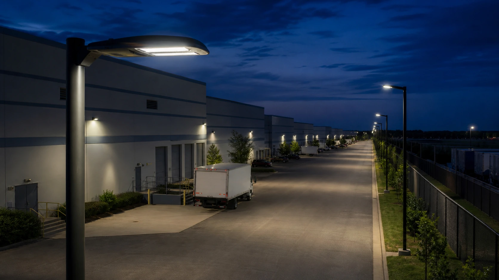
Service roads around industrial, logistics or public facilities need dependable guidance for maintenance vehicles and occasional pedestrians without the visual intensity of a main arterial road.
Road width, curves, loading entrances, fences, gates and adjacent process areas define pole spacing and optical direction.
Service roads around industrial, logistics or public facilities need dependable guidance for maintenance vehicles and occasional pedestrians without the visual intensity of a main arterial road.
Send road alignment, width, gates, pole options, operating hours and nearby sensitive areas.
Use simple single-sided or staggered layouts with controlled tilt. Coordinate poles with security fencing and vehicle access.
Road width, curves, loading entrances, fences, gates and adjacent process areas define pole spacing and optical direction.
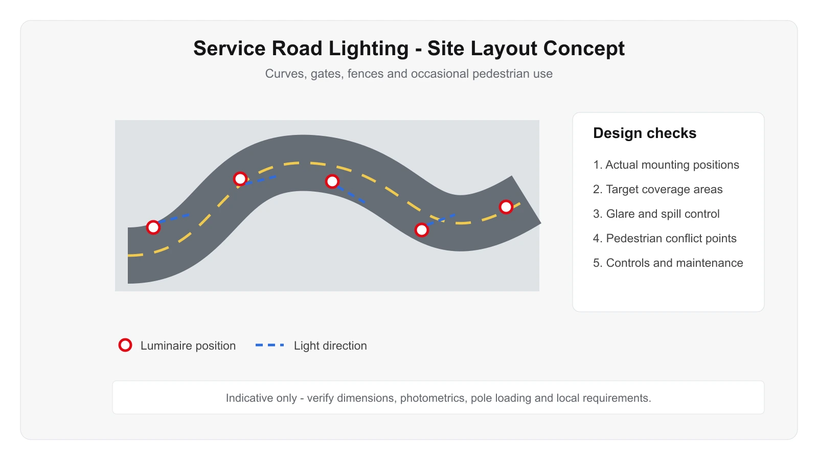
Use this only as a visual reference for mounting and coverage logic. The final design must follow the real project.
Focus on route continuity, obstacle detection, gate recognition and low spill into adjacent properties.
Schedule or dim according to operating hours; maintain appropriate security levels where roads remain active overnight.
Consider CCTV, utility lines, dust, weather and snow / water accumulation where relevant.
Consider CCTV, utility lines, dust, weather and snow / water accumulation where relevant.
Existing utility poles may offer mounting opportunities, but verify structural suitability and electrical isolation.
These are project starting points, not universal specifications. Final wattage, optics, accessories and controls should follow the project calculation and installation conditions.
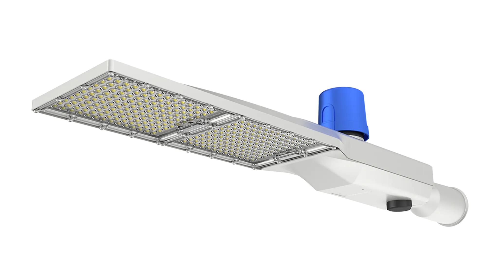
Evaluate this product against the actual mounting height, optics, environment, controls and maintenance requirements for this application.
View product →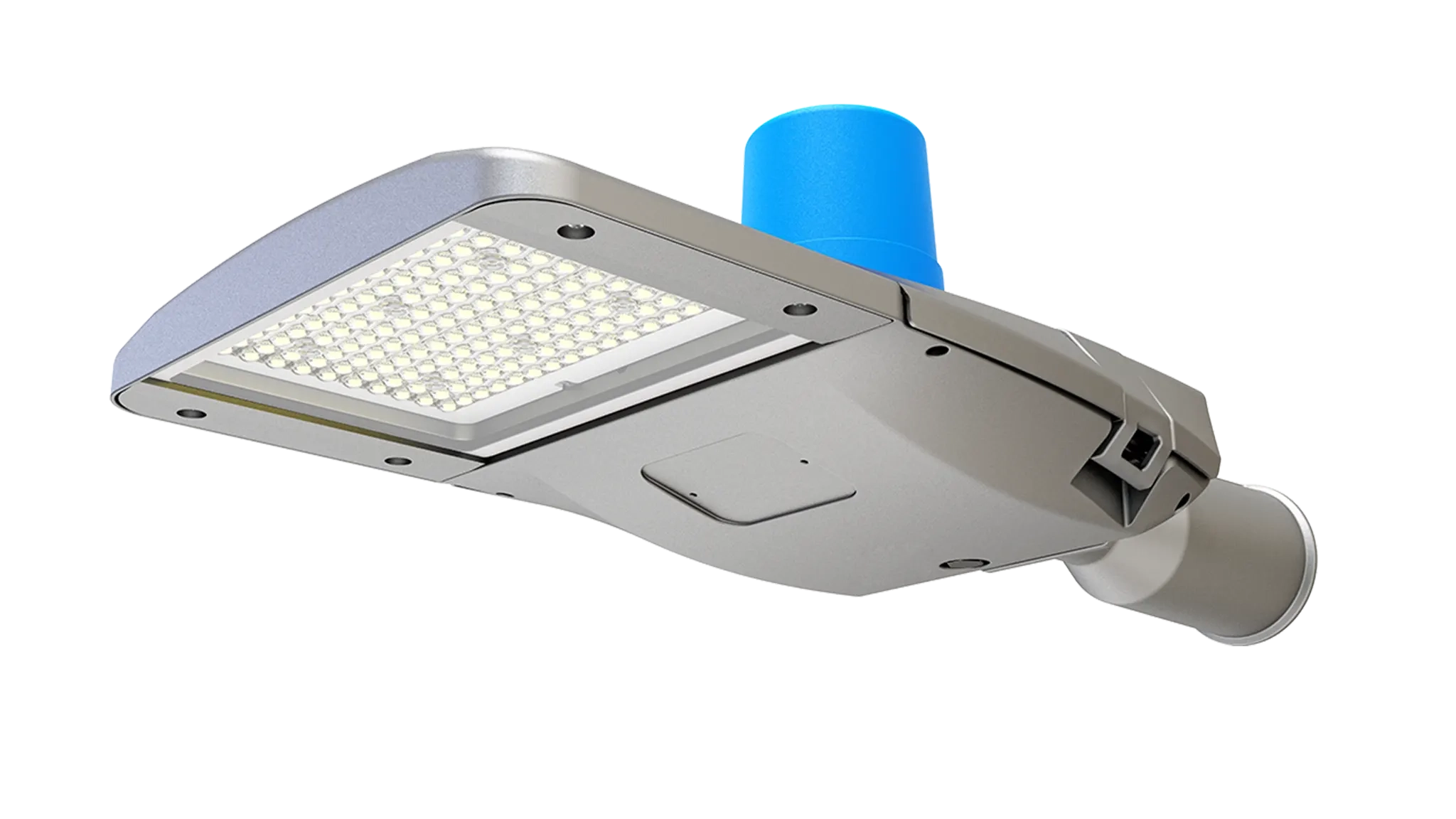
Evaluate this product against the actual mounting height, optics, environment, controls and maintenance requirements for this application.
View product →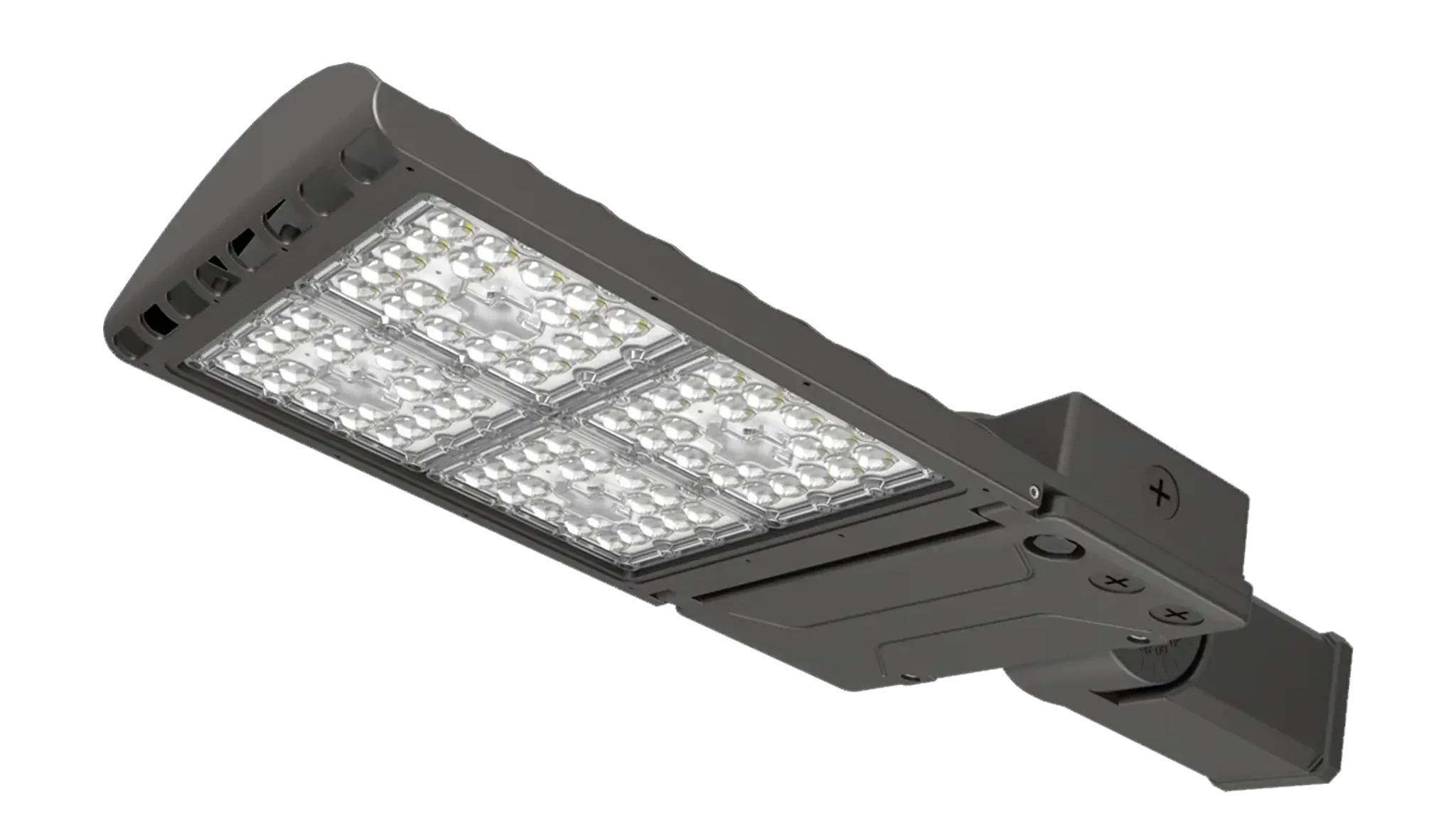
Evaluate this product against the actual mounting height, optics, environment, controls and maintenance requirements for this application.
View product →Send road alignment, width, gates, pole options, operating hours and nearby sensitive areas.
Send the project drawing and mounting information so the optical and product selection can be reviewed against the real site.
These answers are general engineering guidance. Project-specific requirements should always take priority.
Start from the real geometry, mounting positions, operating zones and target visual tasks. Pole or fixture quantity should then be confirmed by photometric calculation rather than copied from a generic example.
Often yes, but structural condition, wind / vibration loading, spacing, electrical condition and compatibility with the new optical strategy should be checked first.
Yes. Zoning, dimming, sensors and schedules affect driver selection, wiring and commissioning. Controls should fit the site operating policy and maintenance capability.
A site or floor plan, mounting height, existing fixture information, target performance, operating hours, environmental conditions and clear photos of the installation area.
No. They are engineering references only. Final mounting positions, fixture quantities, beam distributions and aiming angles should be verified for the actual project.