Why this application needs its own lighting approach
Parking and campus lighting must reveal vehicles, pedestrians, curb lines and building approaches without producing harsh bright spots or excessive light at property boundaries.

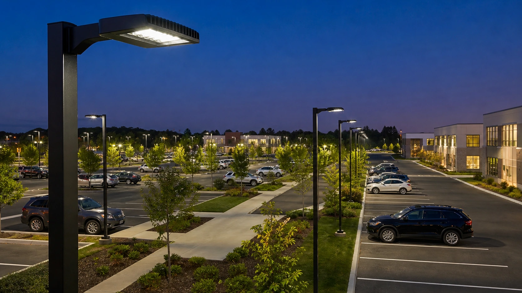
Parking and campus lighting must reveal vehicles, pedestrians, curb lines and building approaches without producing harsh bright spots or excessive light at property boundaries.
Map parking rows, drive aisles, pedestrian paths, building entrances, landscaping, EV areas and CCTV positions. Pole placement should avoid blocking parking bays or creating large shadow zones behind trees.
Parking and campus lighting must reveal vehicles, pedestrians, curb lines and building approaches without producing harsh bright spots or excessive light at property boundaries.
Provide parking layout, pole locations / heights, building entrances, pedestrian routes and operating hours.
Perimeter and internal poles can be combined. Use asymmetric distributions from edges where possible and reserve central poles for large open areas that need multi-directional coverage.
Map parking rows, drive aisles, pedestrian paths, building entrances, landscaping, EV areas and CCTV positions. Pole placement should avoid blocking parking bays or creating large shadow zones behind trees.
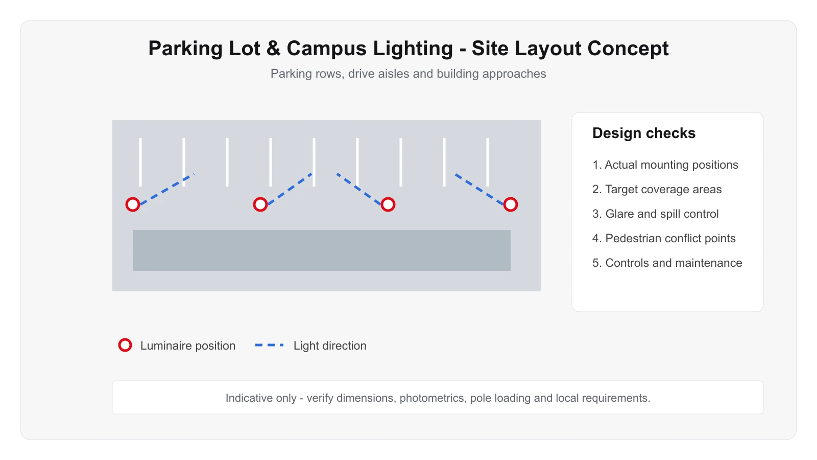
Use this only as a visual reference for mounting and coverage logic. The final design must follow the real project.
Prioritize pedestrian visibility, vertical recognition near vehicles, uniformity, glare control, CCTV support and safe transitions at entrances.
Time scheduling, photocell operation, motion-based setback and campus zoning can reduce energy while retaining security lighting.
Review nearby homes, building windows, signage, trees, security cameras and emergency access routes.
Review nearby homes, building windows, signage, trees, security cameras and emergency access routes.
Existing poles may be suitable if spacing and heights align with modern optics; verify circuit condition and avoid simply increasing lumen output.
These are project starting points, not universal specifications. Final wattage, optics, accessories and controls should follow the project calculation and installation conditions.
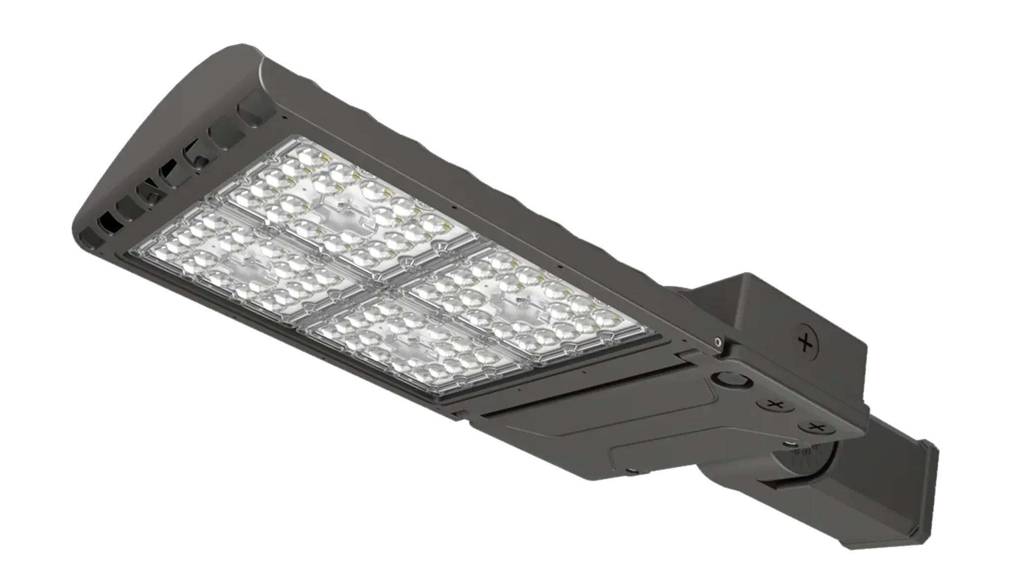
Evaluate this product against the actual mounting height, optics, environment, controls and maintenance requirements for this application.
View product →Evaluate this product against the actual mounting height, optics, environment, controls and maintenance requirements for this application.
View product →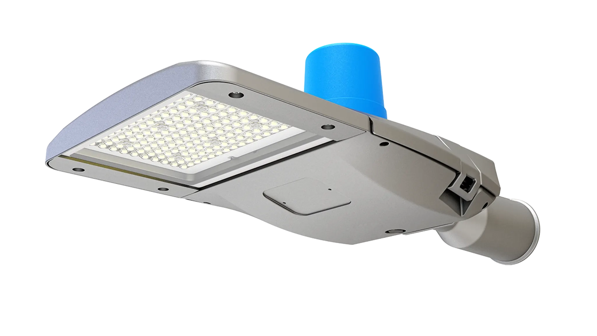
Evaluate this product against the actual mounting height, optics, environment, controls and maintenance requirements for this application.
View product →Provide parking layout, pole locations / heights, building entrances, pedestrian routes and operating hours.
Send the project drawing and mounting information so the optical and product selection can be reviewed against the real site.
These answers are general engineering guidance. Project-specific requirements should always take priority.
Start from the real geometry, mounting positions, operating zones and target visual tasks. Pole or fixture quantity should then be confirmed by photometric calculation rather than copied from a generic example.
Often yes, but structural condition, wind / vibration loading, spacing, electrical condition and compatibility with the new optical strategy should be checked first.
Yes. Zoning, dimming, sensors and schedules affect driver selection, wiring and commissioning. Controls should fit the site operating policy and maintenance capability.
A site or floor plan, mounting height, existing fixture information, target performance, operating hours, environmental conditions and clear photos of the installation area.
No. They are engineering references only. Final mounting positions, fixture quantities, beam distributions and aiming angles should be verified for the actual project.