Why this application needs its own lighting approach
Industrial-park roads serve trucks, employee vehicles, forklifts and pedestrians around gates, factories and loading areas. Lighting must handle mixed speeds and large vehicle geometry.

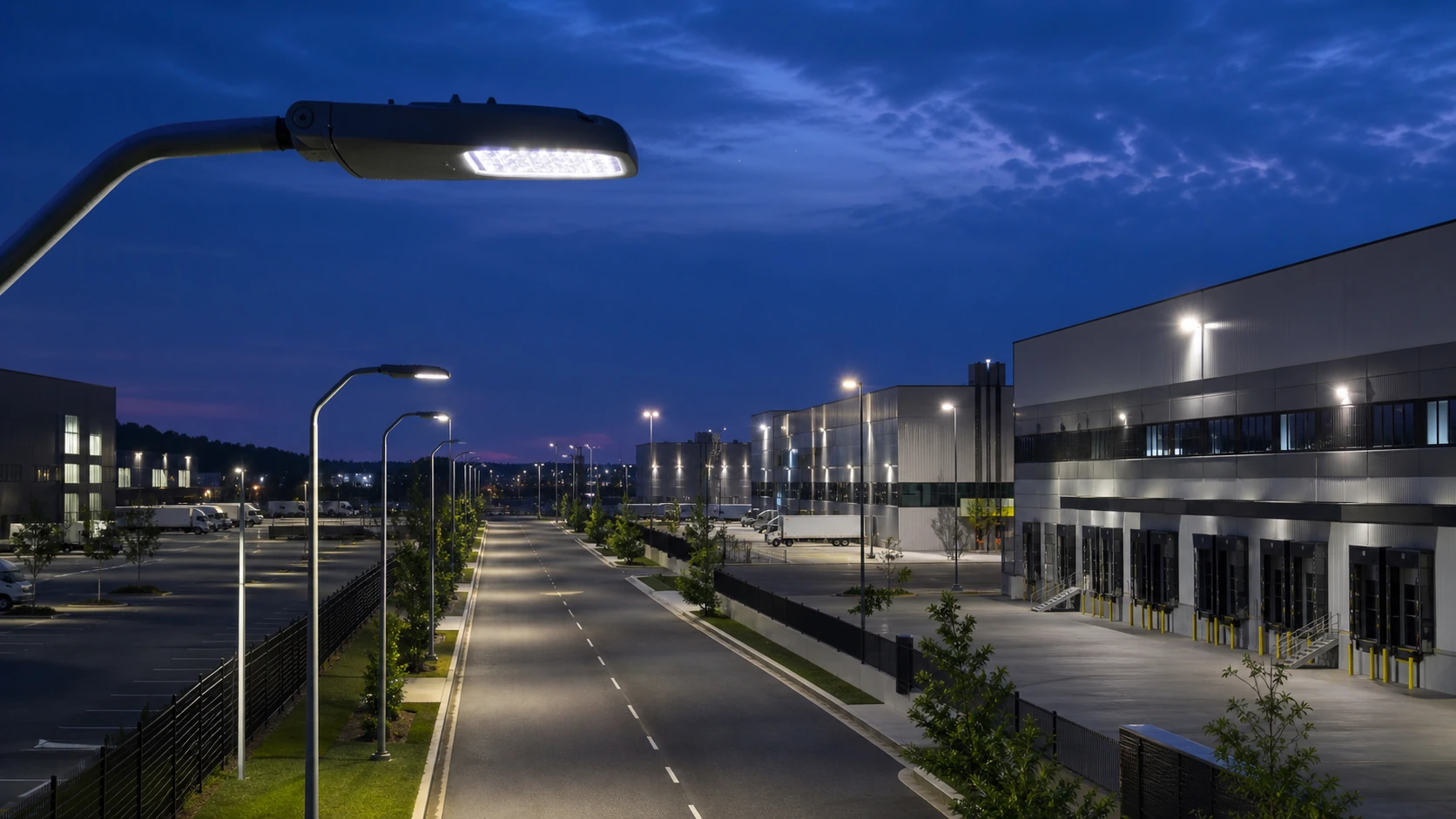
Industrial-park roads serve trucks, employee vehicles, forklifts and pedestrians around gates, factories and loading areas. Lighting must handle mixed speeds and large vehicle geometry.
Model carriageways, truck turning radii, gatehouses, intersections, loading entrances, pedestrian crossings and property boundaries.
Industrial-park roads serve trucks, employee vehicles, forklifts and pedestrians around gates, factories and loading areas. Lighting must handle mixed speeds and large vehicle geometry.
Provide road widths, truck routes, intersections, pole positions and adjacent yard / building lighting.
Roadway poles should be coordinated with gates, signage and truck-clearance zones. Area lighting at junctions or yards should not create competing glare.
Model carriageways, truck turning radii, gatehouses, intersections, loading entrances, pedestrian crossings and property boundaries.
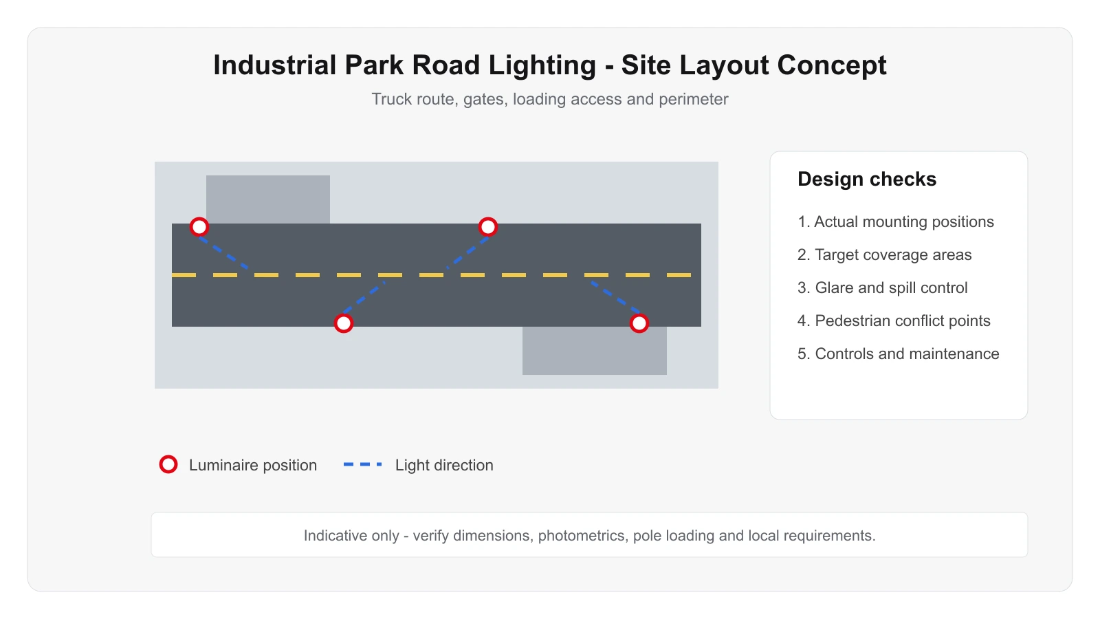
Use this only as a visual reference for mounting and coverage logic. The final design must follow the real project.
Emphasize obstacle visibility, intersection recognition, pedestrian safety and consistent luminance along truck routes.
Schedules can follow shift patterns, with higher levels during peak movements and reduced output during low-traffic hours.
Consider dust, heavy vehicle vibration, pole impact risk, cameras and adjacent industrial yard lighting.
Consider dust, heavy vehicle vibration, pole impact risk, cameras and adjacent industrial yard lighting.
Check how roadway and yard lighting interact; eliminating one source of glare may improve visibility more than simply adding lumens.
These are project starting points, not universal specifications. Final wattage, optics, accessories and controls should follow the project calculation and installation conditions.
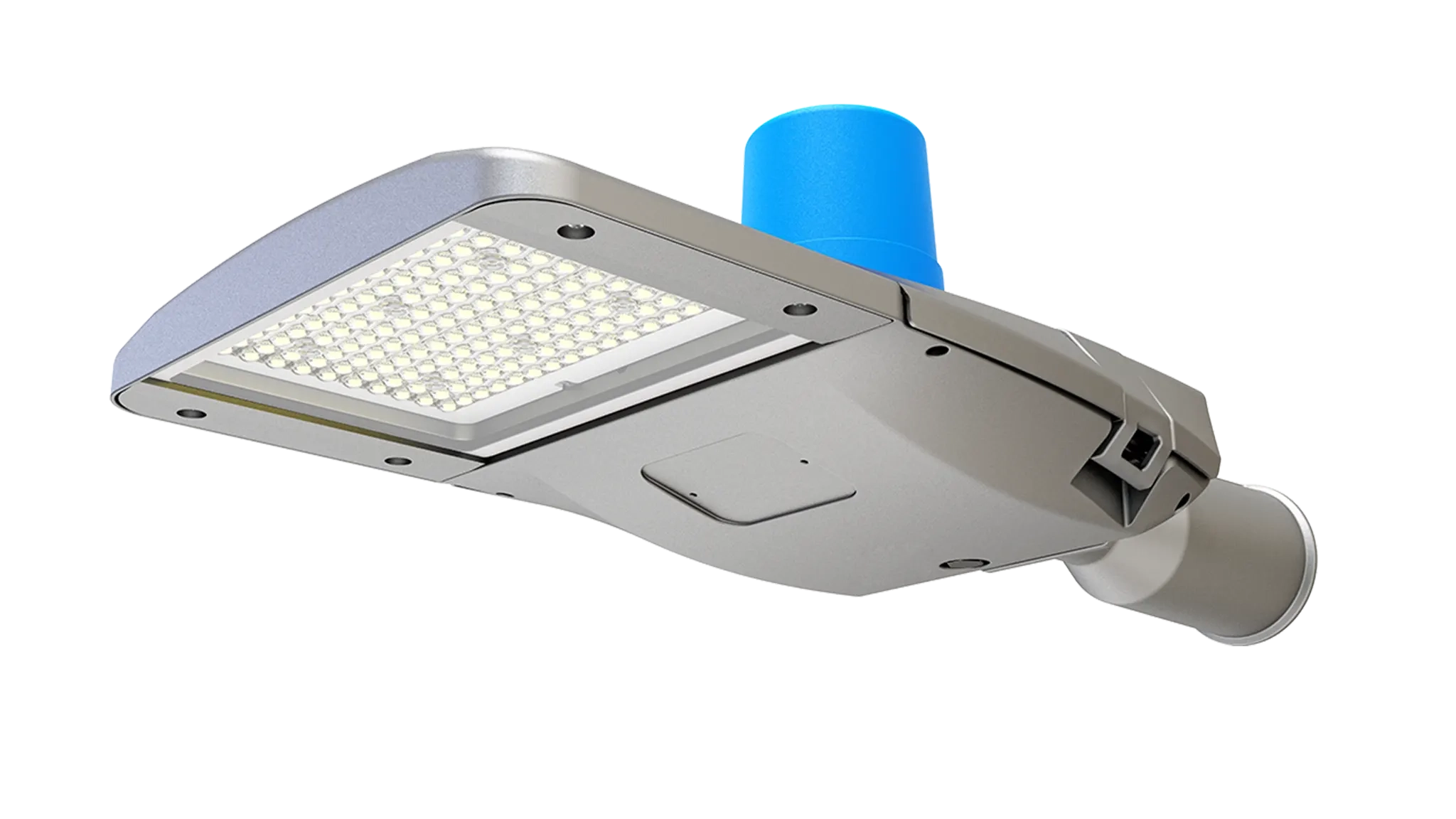
Evaluate this product against the actual mounting height, optics, environment, controls and maintenance requirements for this application.
View product →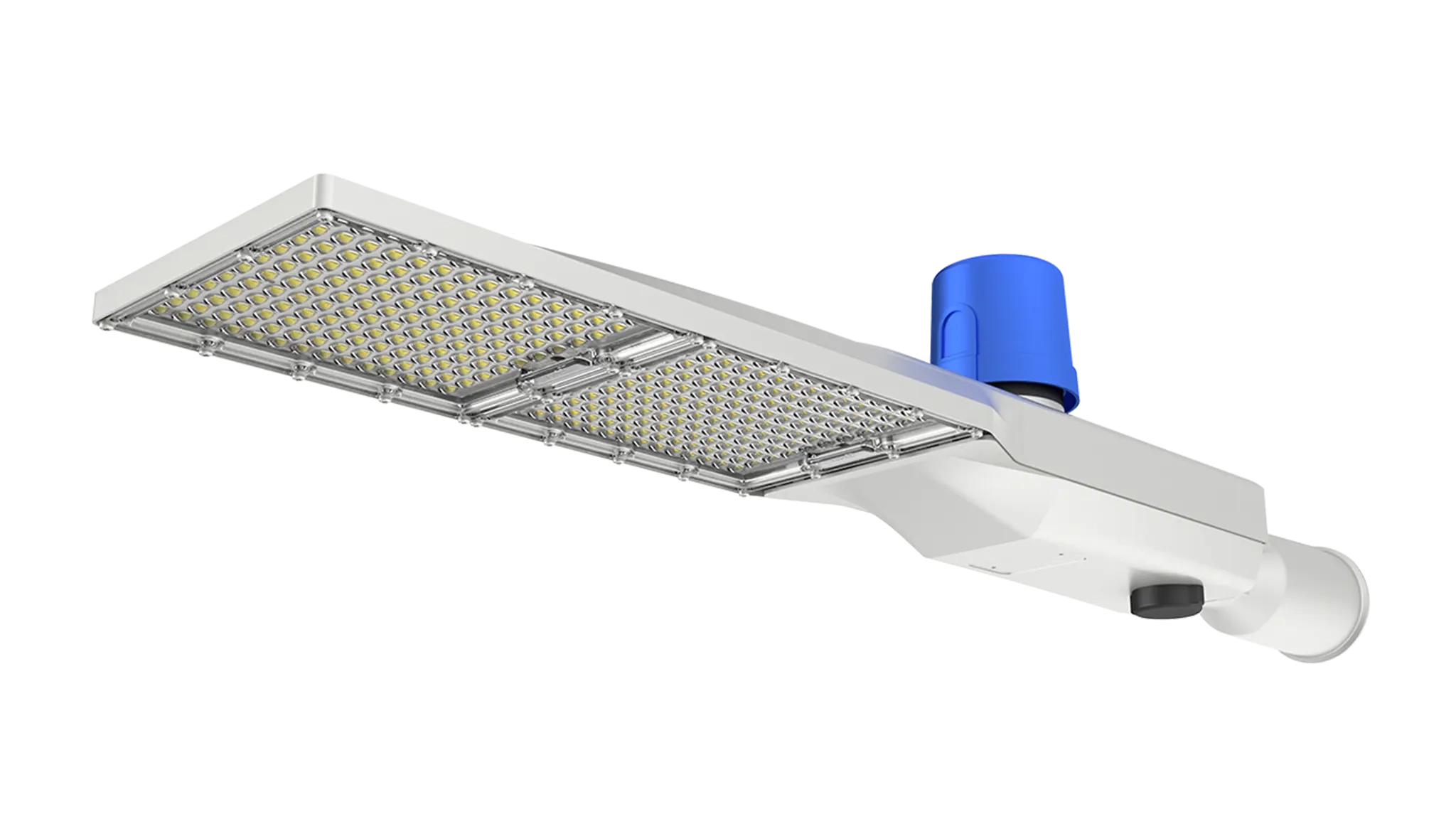
Evaluate this product against the actual mounting height, optics, environment, controls and maintenance requirements for this application.
View product →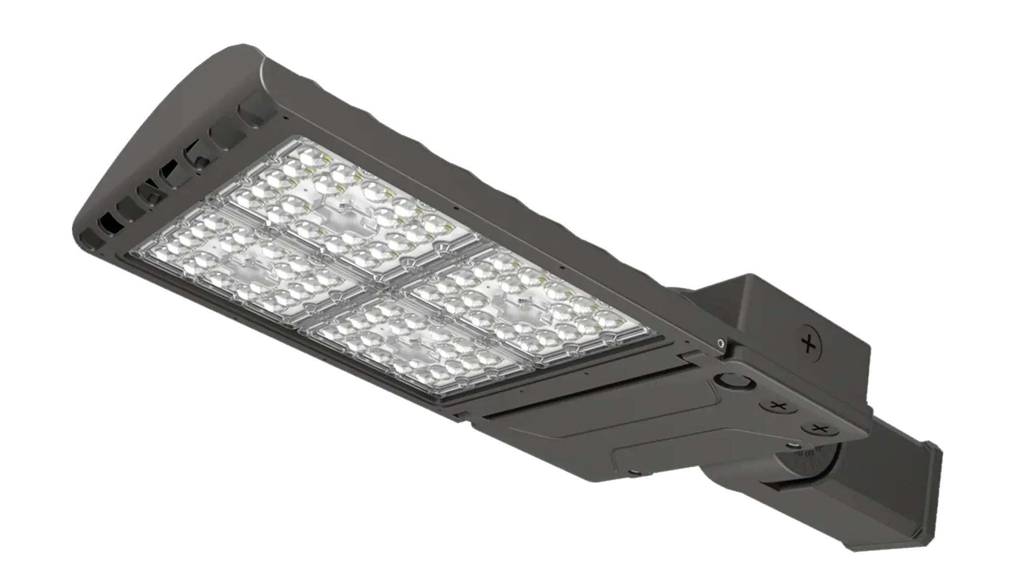
Evaluate this product against the actual mounting height, optics, environment, controls and maintenance requirements for this application.
View product →Provide road widths, truck routes, intersections, pole positions and adjacent yard / building lighting.
Send the project drawing and mounting information so the optical and product selection can be reviewed against the real site.
These answers are general engineering guidance. Project-specific requirements should always take priority.
Start from the real geometry, mounting positions, operating zones and target visual tasks. Pole or fixture quantity should then be confirmed by photometric calculation rather than copied from a generic example.
Often yes, but structural condition, wind / vibration loading, spacing, electrical condition and compatibility with the new optical strategy should be checked first.
Yes. Zoning, dimming, sensors and schedules affect driver selection, wiring and commissioning. Controls should fit the site operating policy and maintenance capability.
A site or floor plan, mounting height, existing fixture information, target performance, operating hours, environmental conditions and clear photos of the installation area.
No. They are engineering references only. Final mounting positions, fixture quantities, beam distributions and aiming angles should be verified for the actual project.