
In This Article
- Three Terms That Answer Different Questions
- ULR Needs an Orientation, Not Just a Percentage
- What Full Cutoff Actually Says
- Read BUG as Three Ratings, Not One Quality Score
- Match Each Claim to the Evidence It Needs
- Why Sports Lighting Makes the Distinction Important
- Assess the View From the Neighbour’s Side
- Evaluate Shielding Before Increasing Wattage
- What to Learn From Musco, AAA-LUX and Signify
- Apply the Same Discipline to ZC’s FL26
- Make the Approved Arrangement Survive Handover
- Frequently Asked Questions
A tender asks for full cutoff lighting. The supplier submits a luminaire data sheet with no upward light in its test position. The contractor installs the floodlights on existing crossarms, tilts them towards the far touchline, and achieves the required average illuminance. A neighbour can still see a bright row of LED lenses from an upstairs window. None of those statements necessarily contradicts the others.
The problem is that a product classification has been used as a substitute for a site assessment. ULR, BUG and full cutoff describe particular aspects of light distribution. They do not, by themselves, prove that an installed sports-lighting scheme will have acceptable glare, boundary spill or night-time impact. This distinction matters before an order is placed, not only when someone complains.
Three Terms That Answer Different Questions
Upward Light Ratio, or ULR, concerns the share of directly emitted light travelling above the horizontal. BUG separates backlight, uplight and glare-related angular zones into ratings. Full cutoff is a legacy distribution classification still encountered in specifications and local ordinances. None is a substitute for knowing where the luminaires are, how they are aimed and where people will view them.
The US Federal Highway Administration explains the move from traditional cutoff categories to the more detailed Luminaire Classification System in its 2012 handbook discussion of luminaire classification. That historical explanation is useful; it should not be mistaken for the current edition of every standard named in a tender.
For procurement, ask three separate questions: what does the tested distribution show, what does the installed arrangement produce, and which agreed limits apply at this site? A supplier who answers only the first question has supplied product information, not completed the environmental assessment.
ULR Needs an Orientation, Not Just a Percentage
A ULR value is meaningful only with its calculation basis. Confirm whether it refers to a luminaire in a stated test orientation or to the installed scheme with every mounting and aiming angle included. The physical horizontal plane at the venue is what matters for upward emission; it does not rotate conveniently with a tilted fitting.
Consider a hypothetical floodlight whose optics place all direct output below the horizontal when mounted level. If the installer raises the front to reach a distant part of the pitch, part of that distribution may move above the real horizontal. The original test result has not become false. It has become insufficient to describe the new installation.
Require the report to identify the photometric file, luminous output, accessory arrangement and orientation behind each result. A screenshot showing a single zero is not enough. The lighting schedule should connect each luminaire identifier to its position and aiming target so that the installed result can be reproduced.
Also separate direct uplight from reflected light. A downward-only luminaire still illuminates turf, paving and other surfaces that reflect some light upwards. Zero direct uplight does not mean zero skyglow or no ecological effect. The ILP GN01/21 guidance addresses reflected upward light as a separate consideration.
What Full Cutoff Actually Says
In the traditional definition, full cutoff requires zero luminous intensity at and above the horizontal, together with a limit on high-angle intensity below it. The historical high-angle criterion is expressed in candela per thousand lamp lumens, not as a percentage of total flux in an angular band. Confusing intensity with flux changes the meaning of the requirement.
The Lighting Research Center’s LESS report records that legacy definition. Modern LED tenders should identify the applicable classification method explicitly rather than relying on a loose phrase inherited from an older lamp specification.
A visible visor is not proof of full cutoff. It may block light towards one observer while leaving another direction exposed. A flat glass front is not proof either. The relevant evidence is the complete photometric distribution for the specified configuration and its permitted mounting orientation.
Do not delete the phrase from a tender merely because it is old terminology. A planning condition or local ordinance may still use it. Instead, ask the designer to state what evidence satisfies that requirement and how any proposed equivalent classification will be accepted. Equivalence is a decision for the responsible reviewer, not a line added by a salesperson.
Read BUG as Three Ratings, Not One Quality Score
BUG means Backlight, Uplight and Glare. Its ratings describe output in defined angular regions. They help screen distributions, but they are not three measurements taken at the nearest house. The letter G is especially easy to misuse: it does not report the discomfort of a particular resident or the visibility of a driver approaching a junction.
Backlight also depends on the luminaire’s orientation. What is identified as the back of a product needs to be related to the actual site. Rotating the fitting can put that distribution towards a different boundary. A purchase comparison that ignores rotation can reward the wrong optic.
Ask for the underlying photometric file and report settings whenever a rating is supplied. Confirm the exact output version and whether the classification is applicable to the intended sports-floodlight arrangement. Photometric Toolbox documentation illustrates why classifications can have applicability conditions; a software label should not be copied without reading its basis.
Lower category values may be useful for a particular specification, but buying the lowest-looking string without checking field coverage is not a design method. The selected optic must deliver the required task light while controlling unwanted directions.
Match Each Claim to the Evidence It Needs
| Claim in a quotation | Useful supporting evidence | Still not established |
|---|---|---|
| Low ULR | Calculation basis, orientation and configuration | Window illuminance or observer glare |
| Full cutoff | Relevant distribution test and mounting limits | Acceptability after arbitrary tilting |
| BUG rating supplied | Rating method and matching photometric file | Every receptor’s experience on site |
| Visor included | Accessory identification and matching photometry | Zero spill in every direction |
| Low boundary readings | Agreed planes, points and operating modes | No visible-source complaint elsewhere |
Use this distinction during bid clarification. A missing site calculation is not necessarily evidence of a bad luminaire, but it is an unresolved project risk. Put a named owner and a completion date against that risk before treating the offer as technically complete.
Why Sports Lighting Makes the Distinction Important
A road luminaire usually serves a relatively predictable strip of ground. A sports floodlight may have to reach across a wide pitch, illuminate a ball above it and work around restricted pole locations. Those requirements make aiming, beam selection and the surrounding geometry particularly important. A rule copied from a car park cannot be assumed to resolve the whole sports brief.
Existing poles often create the hardest commercial decision. Reusing them can reduce civil work, but their positions may force aggressive aiming towards a sensitive boundary. Before deciding that a more powerful fitting is necessary, compare an alternative optic, a different allocation of luminaires between poles, or a revised mounting arrangement.
Every alternative should be tested against the same playing area and environmental assessment points. Otherwise, a proposal can appear cleaner simply because the calculation omitted the difficult edge of the pitch or the upper-floor windows. The related PA and TA reference-area guide explains why changing the assessed area changes the result.
Sometimes the responsible recommendation is a layout change rather than a different fixture. That may be unwelcome during budgeting, but discovering it before foundations or crossarms are ordered is less disruptive than trying to hide a beam afterwards.
Assess the View From the Neighbour’s Side
Begin with a receptor schedule: bedrooms, balconies, roads, footpaths and any environmentally sensitive areas identified by the project team. Record heights and viewing directions, not only distances from the fence. A ground-level horizontal grid does not describe light entering a vertical window several metres above it.
For each receptor, agree the relevant metric and the operating period. Window illuminance, source intensity towards an observer, upward emission and road-user glare answer different questions. The assessment should explain why its selected measures address the concern, rather than present a long table of unrelated outputs.
A practical review uses a drawing and a short schedule together. The drawing makes omissions visible; the schedule records criteria, assumptions and results. Include neighbouring luminaires where the agreed method requires them, and distinguish the proposed system’s contribution from the existing background.
Do not promise that passing one calculation will eliminate complaints. For example, England’s official artificial-light nuisance guidance states that there is no fixed level that automatically defines a statutory nuisance. The project still needs a defensible design and an operational response process.
Evaluate Shielding Before Increasing Wattage
A shield changes where light can travel. It can also remove useful light from an intended target. That is why adding a visor after the calculation and assuming the original field results remain valid is not a satisfactory acceptance method.
Compare the shielded and unshielded configurations using matching data. Check the far side of the pitch, uniformity and any required vertical planes as well as the affected boundary. If extra output is proposed to recover lost illumination, recalculate unwanted light too. A change intended to solve one receptor can increase exposure at another.
Keep the bill of materials specific. Record visor type, orientation, fixing arrangement and the luminaire variant it fits. Include mechanical review where accessories change projected area or loading. Do not let an installer improvise a sheet-metal extension without the manufacturer’s and responsible engineer’s review.
The commercial comparison should show the complete compliant arrangement. A lower fixture price is not a saving if the project later needs new brackets, extra access visits or restrictions on bookable evening hours.
What to Learn From Musco, AAA-LUX and Signify
Musco’s system brochure describes optics, visoring and aiming as parts of an integrated installation. AAA-LUX’s published FAQ links directional control with different operating levels across areas and times. Signify’s ArenaVision accessory instructions show dedicated spill-control louvers and aiming equipment.
The transferable lesson is to specify a controllable, reproducible installation. These manufacturers’ proprietary products and commercial guarantees are not international standards, and their descriptions do not establish equivalence with another manufacturer’s offering.
For a ZC procurement, turn that lesson into explicit deliverables: configuration-specific photometry, a luminaire schedule, aiming instructions, agreed operating scenes and an acceptance plan. Compare the evidence and responsibilities included in each bid. Do not compare a complete-system contract with a luminaire-only quotation as though their scope were identical.
Apply the Same Discipline to ZC’s FL26
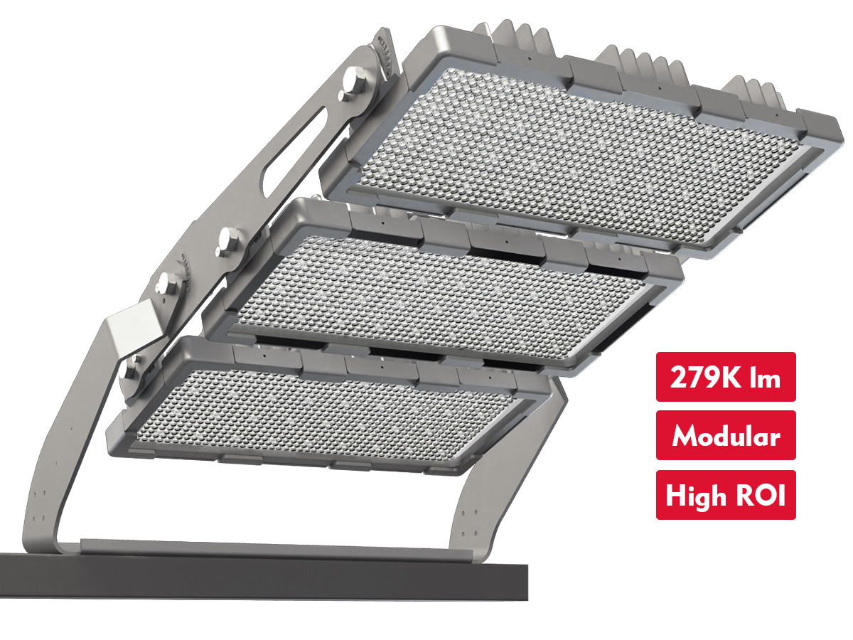
ZC’s FL26 specification, version 1.3, documents selectable wattage, optical configuration options, an optional visor and an aiming scale. It also describes integrated, bracket-mounted and centralised pole-box driver arrangements. These are useful configuration choices, not an automatic ULR, BUG or low-glare certification.
The visor is relevant when a particular direction needs screening. The aiming scale can help communicate an installation setting. Selectable output can help match the ordered configuration to the design. None of these features removes the need to calculate the actual scheme and verify the final settings.
Ask ZC to identify the exact combination being quoted, including the photometric file that represents the selected optic and accessory. Confirm the current specification revision before purchase. If a tested file for the proposed combination is unavailable, keep that item open rather than filling the gap with a similar model’s rating.
For distributors and contractors, this is a practical supplier position: a documented luminaire configuration coordinated with the project’s designer. It does not imply that ZC is providing local planning approval, an independent environmental assessment or a competitor’s turnkey guarantee. Those responsibilities belong in the contract.
Make the Approved Arrangement Survive Handover
Before installation, issue one approved schedule with luminaire identifiers, coordinates, heights, output settings, accessories and aiming targets. Withdraw superseded versions. A well-calculated scheme can be undermined by a contractor using an earlier drawing from an email attachment.
At commissioning, record the installed configuration and investigate differences before adjusting output. Photograph aiming marks and fitted accessories where access permits. Confirm the agreed training and competition modes, time controls and any authorised override behaviour. Repeat the relevant checks after a material change.
Keep the baseline for maintenance. A replacement driver with a different setting or a floodlight re-aimed after servicing can change the installation without changing its appearance from the ground. The operator needs to know which changes require review.
For a project quotation, send ZC the site drawing, pole details, sensitive receptor locations and required operating modes. Request an identified configuration and a clear list of assumptions. That is a more useful starting point than asking for a high-wattage fitting labelled full cutoff.
Frequently Asked Questions
Does full cutoff lighting guarantee no light pollution?
No. It describes a distribution under specified conditions. Installed aiming, reflected light, operating hours and exposure at neighbouring receptors still need assessment. It should not be sold as a guarantee of zero skyglow or no complaints.
Is U0 the same as zero glare?
No. U refers to the uplight component of a BUG rating. It does not measure every observer’s glare experience. Source direction, installation geometry and the applicable glare assessment remain separate considerations.
Can a visor be fitted after the lighting design?
It may be possible, but the change needs review. Obtain suitable photometric and mechanical information, then recheck task lighting and off-site effects. Do not assume that the original unshielded calculation still represents the modified installation.
What should accompany a full-cutoff quotation?
Request the classification basis, permitted orientation, exact luminaire and accessory identifiers, matching photometry, installed aiming schedule and site assessment scope. Clarify who confirms compliance with the project’s planning or regulatory requirements.
Header: AI-generated application illustration based on ZC FL26 product references, not a completed project photograph or evidence of lighting compliance. Technical sources checked 2026-9-8.