Why this application needs its own lighting approach
Crusher areas, heavy process lines and machinery zones can subject luminaires to airborne dust and continuous vibration that affect optics, fasteners and electrical connections.


Crusher areas, heavy process lines and machinery zones can subject luminaires to airborne dust and continuous vibration that affect optics, fasteners and electrical connections.
Map dust sources, machinery, vibration zones, conveyor lines, maintenance products and airflow that transports particles.
Crusher areas, heavy process lines and machinery zones can subject luminaires to airborne dust and continuous vibration that affect optics, fasteners and electrical connections.
Send dust source, vibration level / equipment type, mounting structure, cleaning interval and environmental temperature.
Use secure mechanical mounting with appropriate locking hardware and keep luminaires clear of direct material impact paths. Smooth external surfaces can reduce dust accumulation.

Map dust sources, machinery, vibration zones, conveyor lines, maintenance products and airflow that transports particles.
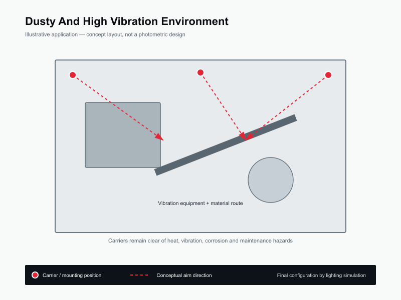
Use this only as a visual reference for mounting and coverage logic. The final design must follow the real project.
Maintain useful task light as optics become dirty between cleaning cycles; avoid narrow beams that lose effective coverage when misalignment occurs.
Keep controls simple and robust in high-vibration areas unless the site has a proven industrial control architecture.
Review IP / IK, vibration resistance, fasteners, cable glands, dust loading, cleaning method and ambient temperature.
Review IP / IK, vibration resistance, fasteners, cable glands, dust loading, cleaning method and ambient temperature.
Inspect old brackets, conduits and junction boxes for fatigue before reusing them.
These are project starting points, not universal specifications. Final wattage, optics, accessories and controls should follow the project calculation and installation conditions.
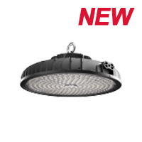
Evaluate this product against the actual mounting height, optics, environment, controls and maintenance requirements for this application.
View product →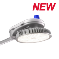
Evaluate this product against the actual mounting height, optics, environment, controls and maintenance requirements for this application.
View product →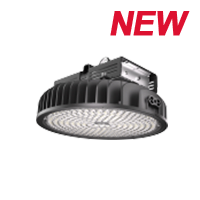
Evaluate this product against the actual mounting height, optics, environment, controls and maintenance requirements for this application.
View product →Send dust source, vibration level / equipment type, mounting structure, cleaning interval and environmental temperature.
Send the project drawing and mounting information so the optical and product selection can be reviewed against the real site.
These answers are general engineering guidance. Project-specific requirements should always take priority.
Start from the real geometry, mounting positions, operating zones and target visual tasks. Pole or fixture quantity should then be confirmed by photometric calculation rather than copied from a generic example.
Often yes, but structural condition, wind / vibration loading, spacing, electrical condition and compatibility with the new optical strategy should be checked first.
Yes. Zoning, dimming, sensors and schedules affect driver selection, wiring and commissioning. Controls should fit the site operating policy and maintenance capability.
A site or floor plan, mounting height, existing fixture information, target performance, operating hours, environmental conditions and clear photos of the installation area.
No. They are engineering references only. Final mounting positions, fixture quantities, beam distributions and aiming angles should be verified for the actual project.